Configure Tunnels with Azure IPsec
Microsoft Azure provides multiple edge-device options to deploy an IPsec tunnel between Azure Virtual Network and Umbrella. This document focuses on the Azure Virtual Network Gateway and Cisco Cloud Services Router (CSR) 1000V options.
Table of Contents
Azure Virtual Network Gateway
The Azure Virtual Network Gateway is deployed as a virtual machine (VM) and works as a site-to-site virtual private network (VPN) concentrator as well as remote access VPN.
As a site-to-site VPN concentrator, the Virtual Network Gateway can work in the following modes:
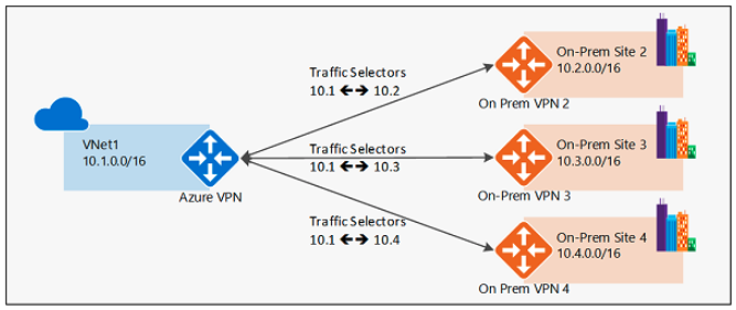
- Policy-based – Internet Key Exchange (IKE) Security Association negotiates specific traffic selector network pairs, for example:
10.0.0.0/24to and from192.168.0.0/24. This mode can be used with Umbrella only if one source subnet will be part of the VPN; for example, 10.0.0.0/16 to/from 0.0.0.0/0. If there are multiple source subnets, Umbrella will be able to negotiate only one traffic selector pair and the remaining child security association containing the other traffic selector pair (other subnets) will fail to negotiate.
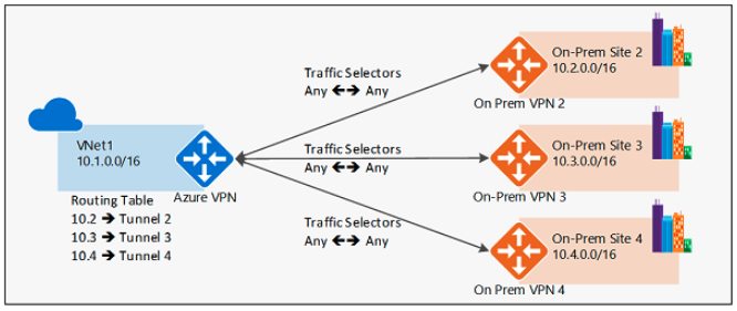
- Route-based – IKE Security Association negotiates any-any traffic selector (0.0.0.0/0 to/from 0.0.0.0/0) and routing is used to forward traffic to different IPsec tunnels. This is the preferred method and the one described in this document.
Deploy Virtual Network Gateway (VNG)
The IPsec tunnel is sourced from the Virtual Network Gateway. If you already have a Virtual Network Gateway deployed in your environment, you can skip this section.
- From the Azure admin portal, navigate to All resources > Add.
- Search for Virtual Network Gateway and add a new gateway.
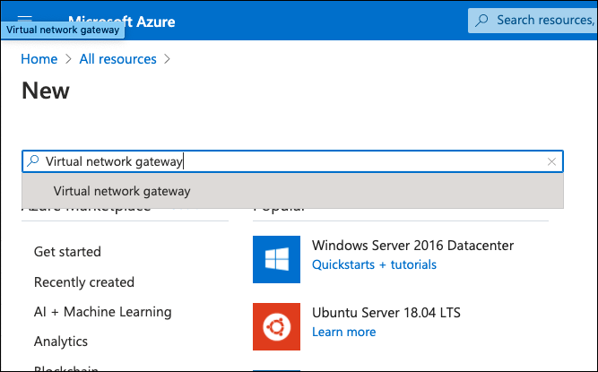
- Click Create.
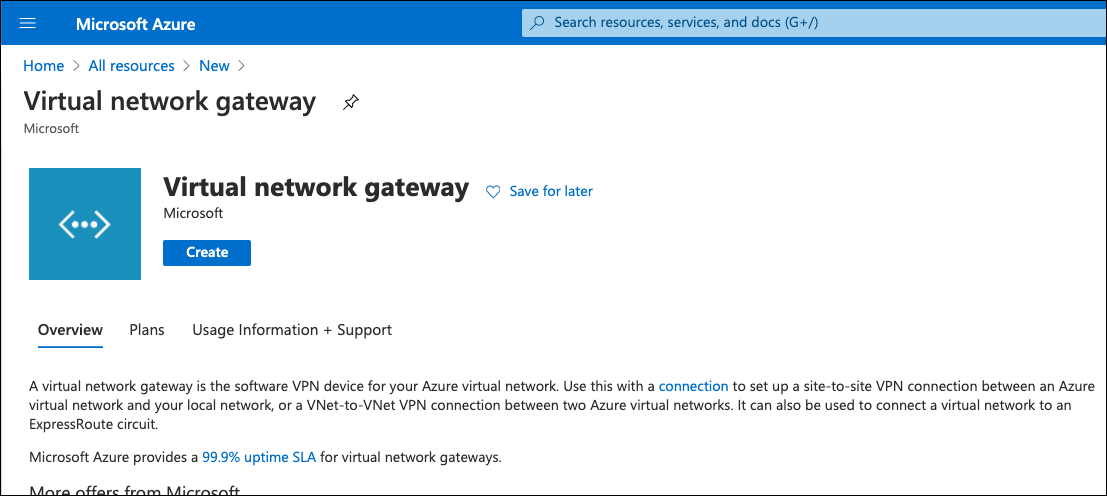
- On the Virtual Network Gateway configuration page provide a name, choose a region, gateway type VPN, VPN Type Route-based, the size of the VNG (SKU), a virtual network—if you don’t have a gateway subnet create one, this is the special subnet used in the virtual gateway inside interface—and create a new public IP or choose an existing one. This public IP is important as it will be used as the IKEv2 Identity.
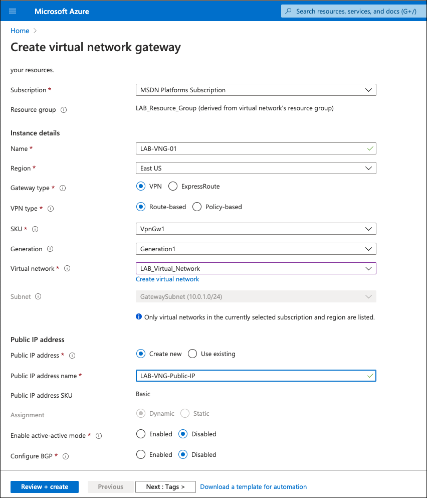
- Click Review + create and then Create.
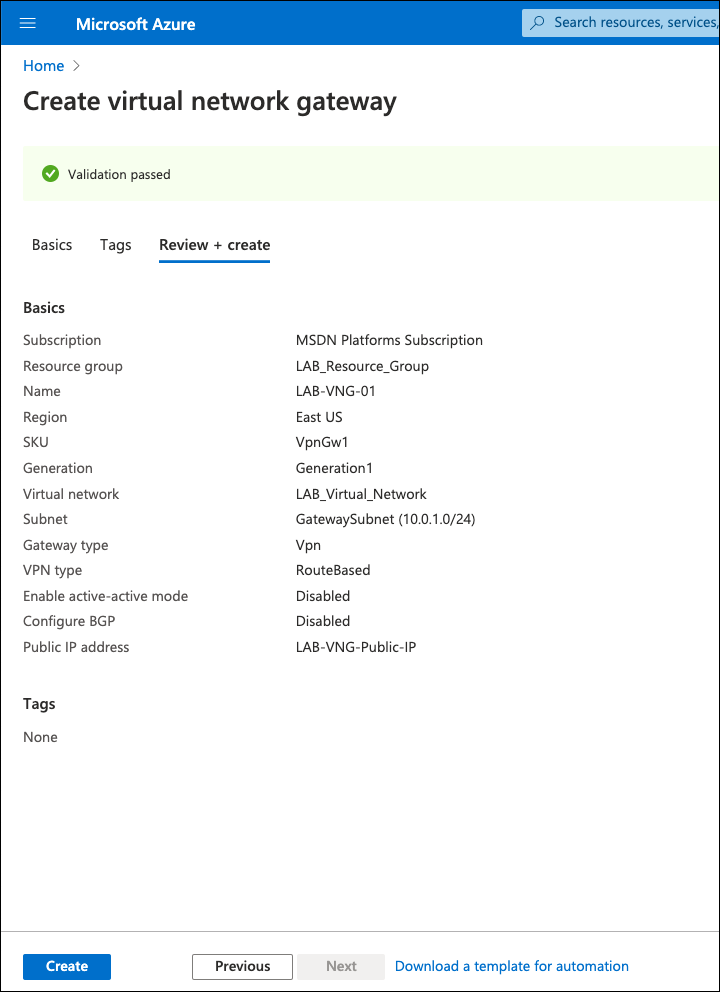
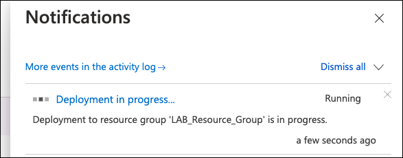
Note: The Virtual Network Gateway can take up to 45 minutes to deploy. You can check its status under Notifications.
After deployment is completed, the Virtual Network Gateway is available under All Resources. From the VNG overview page, you can find the public IP address assigned to the gateway. This IP is required when adding the tunnel through the Umbrella dashboard.
Configure Azure VNG IPsec VPN
Set up the IPsec VPN connection between Azure and Umbrella.
- Navigate to Connections under the just created or existing VNG and click Add.
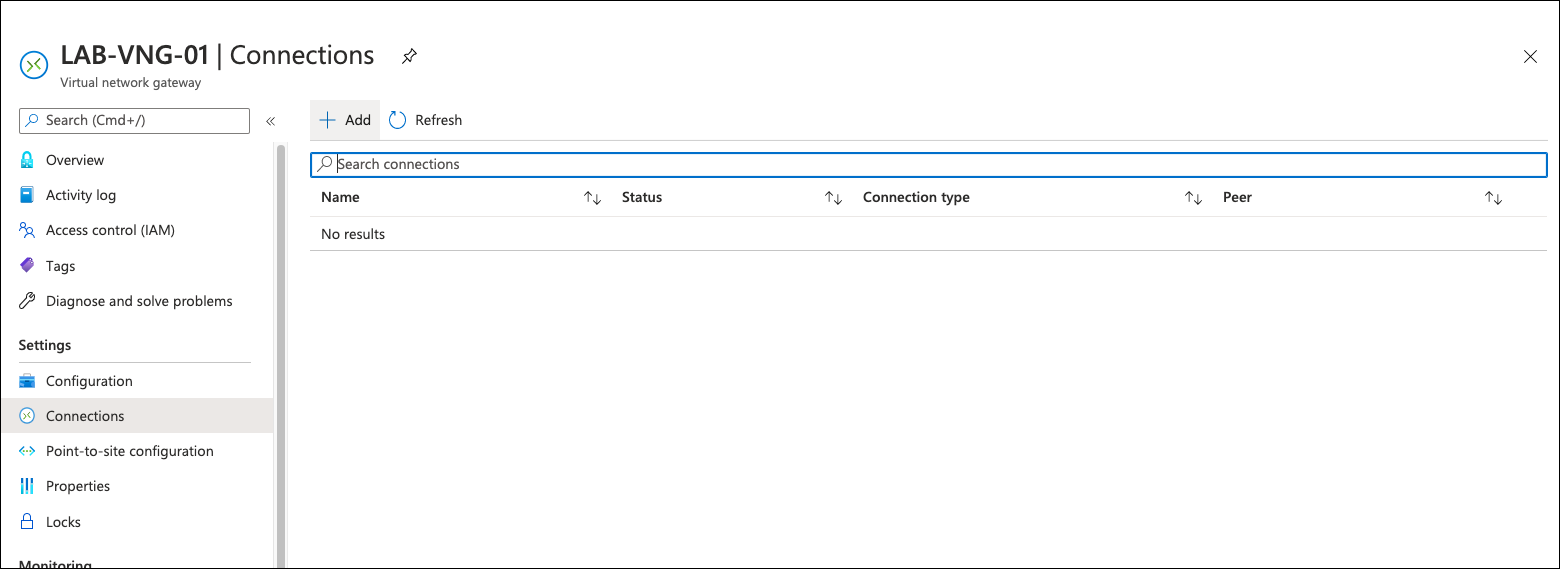
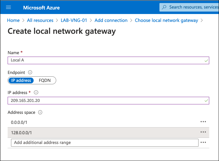
- Select the connection type Site-to-site (IPsec) and under Local Network Gateway, click Choose a local network gateway, and then Create new.
A local network gateway is the remote site—the other side of the IPsec connection. In this case, one of the Umbrella IPsec data centers. For more information, see Supported IPsec Parameters. - Add a name for the connection, the IP address of one of the Umbrella IPsec data centers, and under Address spaces add the routes.
Because the VPN type is route-based, add the routes to the Umbrella IPsec tunnel. Normally a default route would be added, but Azure does not allow default route (0.0.0.0/0). Thus, two /1 routes are required to cover internet traffic (0.0.0.0/1 and 128.0.0.0/1). If you have more specific routes under another VPN connection—for example, site-to-site between your data center and Azure—the more specific route is selected. Adding these two will not break other VPN connections.
- Navigate to the main connection configuration page, provide a name for the VPN connection, a pre-shared key (PSK), and select IKEv2.
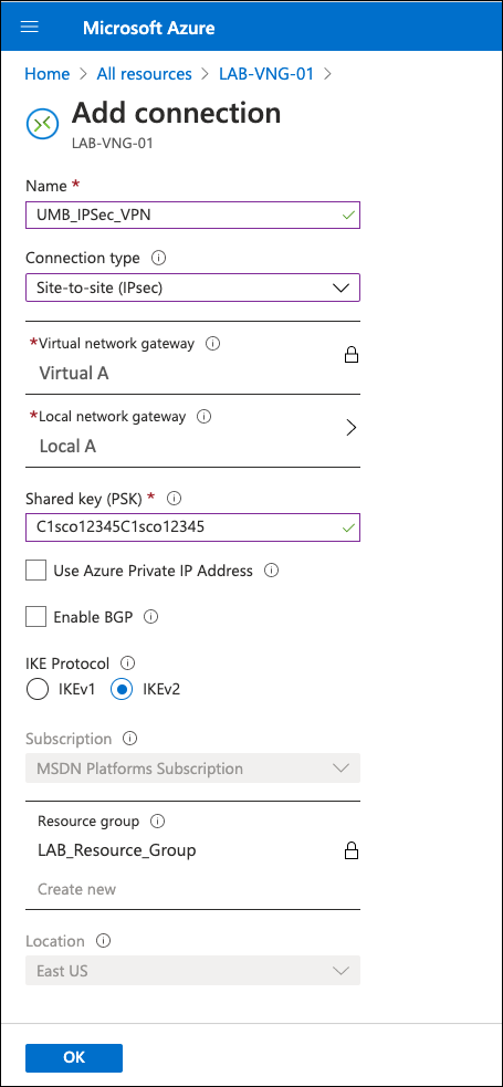
After saving, the VPN status is "Not Connected" because the IKEv2 default policy does not match Umbrella supported ciphers.
- To change the IKE policy, click the VPN connection and navigate to *Configuration.
- Under IPsec/IKE policy, select Custom and then select ciphers,
For more information about ciphers, see Supported IPsec Parameters.
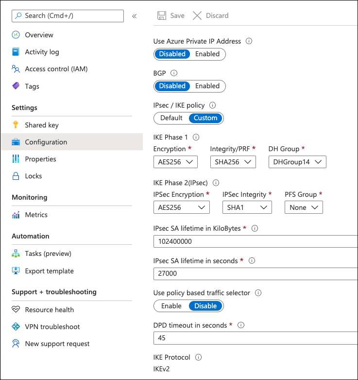
After adding the tunnel in the Umbrella dashboard, the tunnel shows as connected in both the Azure and Umbrella dashboards.
Configure Azure VNG with Umbrella
Azure authenticates to Umbrella IPsec headend through a pre-shared key (PSK) and IKEv2 IP identity. A network identity with Azure Virtual Network Gateway public IP address needs to be added prior to the tunnel creation.
- In the Umbrella dashboard, navigate to Deployments > Core Identities > Networks and click Add.
- Provide a name for the network and the Azure VNG public IP address—found on the Virtual Network Gateway overview page. This network is used as the IKE Identity.
Note: The FQDN identity is not currently supported by Azure Virtual Network Gateway.
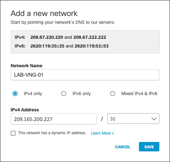
Note: The Azure Virtual Network Gateway public IP address can be found on the Virtual Network Gateway overview page.
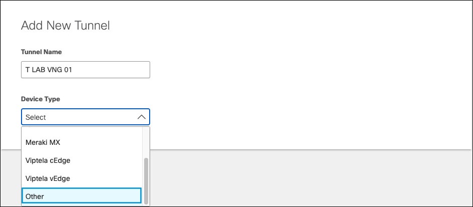
- Navigate to Deployments > Core Identities > Network Tunnels and click Add.
Note: Add a tunnel based on the Other template. - Add a Tunnel Name and from the Device Type drop-down menu, choose Other.
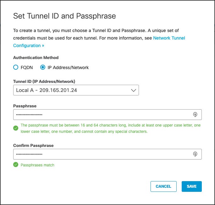
- Select IP Address/Network as Authentication Method. In Tunnel ID drop-down, enter the Azure Virtual Network Gateway network identity (Azure VNG public IP address), provide a pre-shared key (PSK) Passphrase between 16 and 64 characters (the one used in Azure VPN configuration) and click Save.
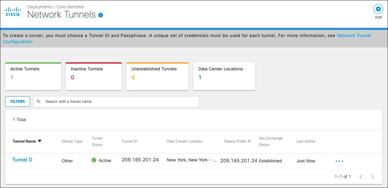
Umbrella lists the tunnel as Not Established until the first IKEv2 INIT message containing the tunnel identity is seen in one of the Umbrella data centers.
Troubleshoot Azure VPN
Azure Virtual Network Gateway includes a diagnostic tool that can be used to debug VPN connection issues.
- Click the Virtual Network Gateway name under All Resources, select Diagnose and Solve Problems and then Connectivity.
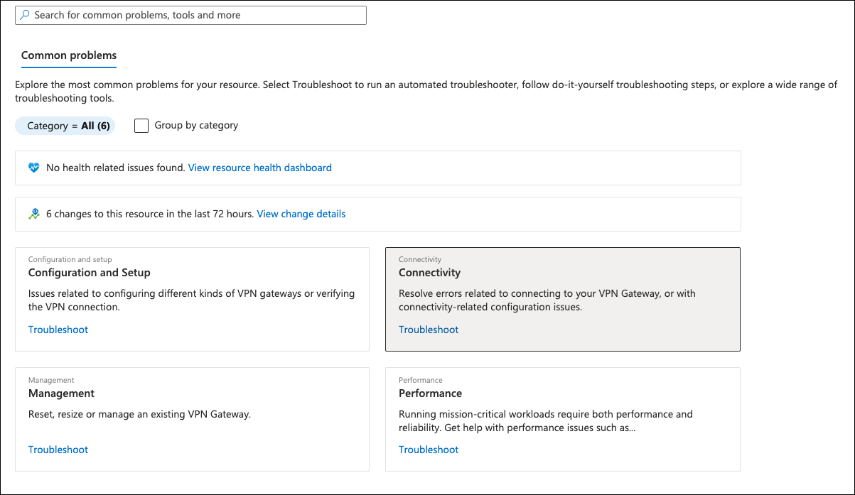
- From the Tell us more about the problem you are experiencing menu, choose Site-to-site VPN connectivity issues.
Cisco Cloud Services Router (CSR) 1000V
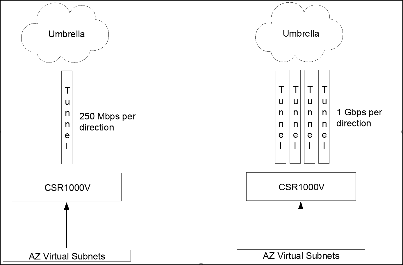
The Cisco Cloud Services Router – CSR1000V is the preferred option for Azure deploys. This virtual router runs Cisco’s IOS-XE software, a features rich routing and security virtual appliance. Some key capabilities include multiple tunnel support for higher throughout (Equal-cost Multi-path routing support) and policy routing (ability to route specific traffic to the tunnel based on source and destination IP/Port/Protocol).
Deploy CSR1000V
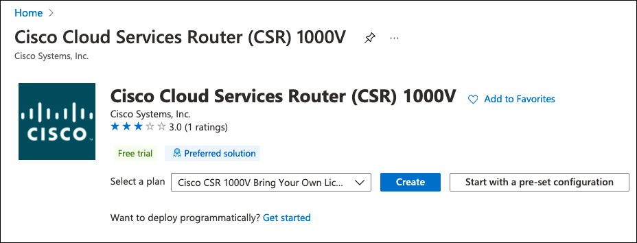
Azure marketplace provides a couple of CSR1000V deployment options including some pre-defined templates. The template options are:
- Create Cisco CSR1000V Solution Deployment —This option gives you the ability to add additional interfaces during the deployment (2, 4, or 8 interfaces). You need one interface for internet connectivity (outside facing interface) and additional interfaces connected to inside Azure virtual networks where hosts reside. Options such as licensing (Azure provided or Bring Your Own License), virtual machine size and software version are also available.
- Cisco Cloud Services Router (CSR) 1000V —This option deploys a CSR1000V with a single network adapter. You can use this option and shutdown the virtual appliance after deployment and add additional interfaces. You can also select licensing and software version.
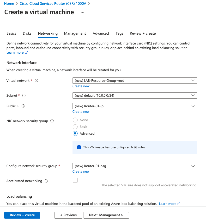
Independent of the deployment method, the CSR1000V is pre-configured with a basic setup: authentication to the device, management address, and interface IP address that defaults to DHCP.
- Choose any method and deploy the CSR1000V. At least two interfaces should exist to facilitate Azure routing changes.
Note: The Azure routing table will be modified to include the CSR1000V as the default gateway to the virtual subnets. - Search for CSR1000V and select one of the above options. Provide information such as hostname and authentication methods, and accept the defaults.
It takes a few minutes to deploy and boot the CSR1000V. After deployment is complete, you can use the Secure Shell Protocol (SSH) to connect to the public IP of the deployed router. A Network Security Group (NSG) is configured as part of the deployment with a rule to allow SSH.
CSR1000V Single Tunnel
For a single tunnel configuration, source the tunnel from the internet facing interface (GigabitEthernet1). Only one IKE over UDP session exists from the router IP address to the Umbrella data center. For multiple tunnels, use a different configuration. For more information, see CSR1000V Multiple Tunnels Load Sharing.
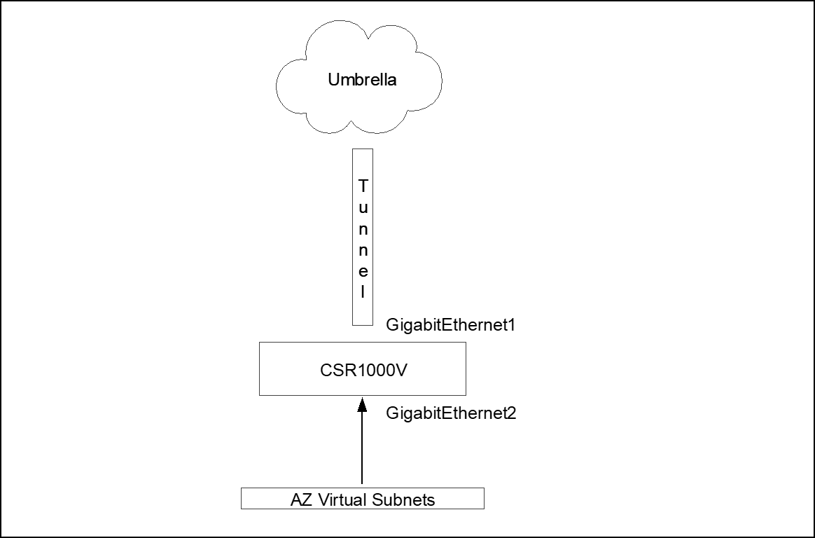
- Create a Virtual Routing and Forwarding (VRF) instance to segment the global routing table (internet facing interface) from the inside routing table (Azure virtual subnet facing interfaces).
!
vrf definition INSIDE
  description *** INSIDE INTERFACES ***
  !
  address-family ipv4
  exit-address-family
!
- The outside interface can remain configured for DHCP IP address assignment. Configure the inside interface with a static IP and add to the INSIDE VRF. Verify your virtual network IP address range for the inside interface IP assignment.
!
interface GigabitEthernet1
  description **** OUTSIDE ****
  ip address dhcp
!
interface GigabitEthernet2
  description **** INSIDE ****
  vrf forwarding INSIDE
  ip address 10.0.1.5 255.255.255.0
!
Add an IKEv2 and IPsec profile as IKEv2 proposal (new or change default) and transform-set. Create the tunnel identity and pre-shared key (PSK) in advance through the Network Tunnels page (Deployments > Core Identities > Network Tunnels).
For Umbrella supported IKEv2 and IPsec parameters, see Supported IPsec Parameters.
!
! *** IKEv2 ciphers ***
!
crypto ikev2 proposal default
 encryption aes-gcm-256
 integrity sha256 sha1
 group 19 20
!
!
! *** IKEv2 authentication parameters (tunnel identity and PSK) ***
!
crypto ikev2 profile UMB_IKE_PROFILE_T1
 match identity remote address 146.112.0.0 255.255.0.0
 identity local email [email protected]
 authentication remote pre-share key XXXXXXXXXXXXXXXXXXXXXXXXXXXXX
 authentication local pre-share key XXXXXXXXXXXXXXXXXXXXXXXXXXXXX
 dpd 10 2 periodic
!
!
! *** Maximum IKEv2 packet size to avoid fragmentation in the path ***
!
crypto ikev2 fragmentation mtu 1300
!
!
! *** IPsec ciphers ***
!
crypto ipsec transform-set UMB_IPSEC_TRANSFORM_SET esp-gcm 256
!
!
! *** IPsec profile linking transform-set and IKEv2 profile, assigned to the tunnel interface ***
!
crypto ipsec profile UMB_IPSEC_PROFILE_T1
 set transform-set UMB_IPSEC_TRANSFORM_SET
 set ikev2-profile UMB_IKE_PROFILE_T1
Virtual tunnel interface configuration
!
! *** Tunnel interface in the INSIDE VRF, sourced from G1 interface and protected by IPsec profile ***
!
interface Tunnel1
 vrf forwarding INSIDE
 ip unnumbered GigabitEthernet1
 !
 ! * TCP Adjust-MSS intercepts TCP handshake and changes MTU to 1300 to avoid fragmentation *
 ip tcp adjust-mss 1300
 !
 tunnel source GigabitEthernet1
 tunnel mode ipsec ipv4
 tunnel destination 146.112.83.8
 tunnel protection ipsec profile UMB_IPSEC_PROFILE_T1
!
!
! *** Azure pre-defined default route in global VRF, router internet access ***
!
ip route 0.0.0.0 0.0.0.0 10.0.0.1
There are two routing options to route traffic to the Umbrella tunnel. The first is through static routing that is added to the inside VRF and sends all traffic to the tunnel, Azure pre-defined. This default route will not overlap as they are in different VRF (different routing tables).
!
ip route vrf INSIDE 0.0.0.0 0.0.0.0 Tunnel1
!
The second option (preferred) is to use policy routing to send the traffic to Umbrella. This option allows more granular control on what should be sent through the tunnel or direct internet access (DIA). Policy routing uses an access list to match the traffic that will be routed and then a route-map to set the tunnel as next hope.
!
! *** Sample Access List with few possible match statements can use one or many of these entries ***
!
ip access-list extended TRAFFIC_TO_UMB
 10 permit ip host 172.16.10.103 any
 20 permit ip any any
 30 permit tcp any any eq www
!
!
! *** Route-map matching the access list and setting the tunnel as next-hop ***
!
route-map ROUTE_TO_UMBRELLA permit 10
 match ip address TRAFFIC_TO_UMB
 set interface Tunnel1
!
!
! *** Route-map assigned to inside interface ***
!
interface GigabitEthernet2
 description **** INSIDE ****
 ip policy route-map ROUTE_TO_UMBRELLA
!
CSR1000V Multiple Tunnels Load Sharing
Single tunnel deployment limits the maximum throughout to the throughput of one tunnel (currently 250Mbps per direction), for higher throughput multiple tunnels should be added and Equal-Cost Multi-Path routing used to distribute the connections among the available tunnels (load sharing).
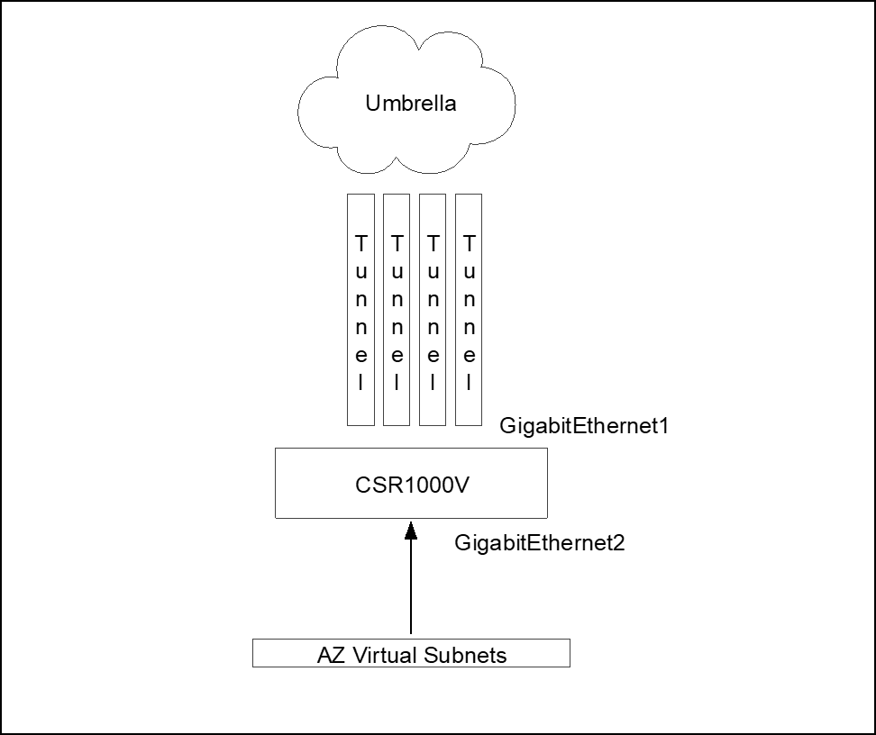
Cisco Express Forwarding
Each connection should always go thought the same tunnels as the Umbrella side. Each tunnel is part of a service chain, so per packet load balancing is not support. It should be per connection load sharing. This is achieved by using Cisco Express Forwarding – CEF universal algorithm (default algorithm in Cisco devices). The universal algorithm creates a hash of source and destination IP and port, and sends each connection to the same next-hop. For more information, see Load-Balancing Algorithms.
In multiple tunnel deployments, each tunnel should be sourced from a different interface and NATed to the outside interface. Umbrella forces NAT transversal so not only IKE connection is over UDP but also ESP is encapsulated in UDP and both IKE and ESP uses source and destination port UDP 4500. The issue is when the router creates multiple tunnels to the same destination address (same Umbrella datacenter). The router does not use a different source port, so all tunnels have the same source IP/Port (for example, 1.2.3.4:4500) and destination IP/Port (for example, 146.112.83.8:4500). The router will only be able to bring one tunnel up as connection information will be exactly the same (all tunnel from 1.2.3.4:4500 to 146.112.83.8:4500) so the router does not know to which tunnel the traffic belongs.
To address this limitation, source each tunnel from a different loopback interface and then traffic from the loopback interface should be NATed (NAT PAT or NAT Overload) to the outside interface. After the NAT process, each tunnel will have a different source port and the router can use the source port to direct the traffic to the right tunnel (tunnel1 from 1.2.3.4:11111 to 146.112.83.8:4500 / tunnel2 from 1.2.3.4:22222 to 146.112.83.8:4500 and so on).
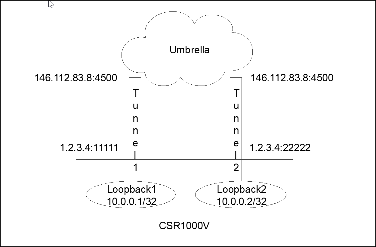
NAT from 10.0.0.0/24 (all loopback interfaces) to outside interface address (1.2.3.4) overload (NAT PAT)
Multiple tunnel configuration is similar to single tunnel configuration. An internal VRF must be added.
!
vrf definition INSIDE
 description *** INSIDE INTERFACES ***
 !
 address-family ipv4
 exit-address-family
!
Interfaces and tunnel source interfaces (loopback) NAT configuration
!
! *** One loopback per tunnel ***
!
interface Loopback1
 ip address 192.168.0.1 255.255.255.255
 ip nat inside
!
interface Loopback2
 ip address 192.168.0.2 255.255.255.255
 ip nat inside
!
interface Loopback3
 ip address 192.168.0.3 255.255.255.255
 ip nat inside
!
interface Loopback4
 ip address 192.168.0.4 255.255.255.255
 ip nat inside
!
!
! *** GigabitEthernet1 Internet facing interface with NAT outside configuration (loopback traffic
!     NATed to this interface) ***
!
interface GigabitEthernet1
 description **** OUTSIDE ****
 ip address dhcp
 ip nat outside
!
!
! *** Inside interface, ideally with static IP ***
!
interface GigabitEthernet2
 description **** INSIDE ****
 vrf forwarding INSIDE
 ip address 10.0.1.5 255.255.255.0
!
!
! *** Access list matching loopback addresses, used in NAT statement ***
!
ip access-list standard TUNNEL_SOURCES
 10 permit 192.168.0.0 0.0.0.255
!
!
! ** NAT traffic from loopback to outside interface address ***
!
ip nat inside source list TUNNEL_SOURCES interface GigabitEthernet1 overload
!
!
! *** Azure pre-defined default route in global VRF, router internet access ***
!
ip route 0.0.0.0 0.0.0.0 10.0.0.1
Crypto configuration includes the IKEv2 cipher (can change existing proposal or add new) and one IKEv2 and IPsec profile per tunnel. Each tunnel has a different IKEv2 identity (different tunnels in Umbrella dashboard).
!
! *** IKEv2 ciphers ***
!
crypto ikev2 proposal default
 encryption aes-gcm-256
 integrity sha256 sha1
 group 19 20
!
!
! *** One IKEv2 profile per tunnel with tunnel identity created in Umbrella dashboard ***
!
crypto ikev2 profile UMB_IKE_PROFILE_T1
 match identity remote address 146.112.0.0 255.255.0.0
 identity local email [email protected]
 authentication remote pre-share key XXXXXXXXXXXXXXXXXXXXXXXXXXXXX
 authentication local pre-share key XXXXXXXXXXXXXXXXXXXXXXXXXXXXX
 dpd 10 2 periodic
!
!
crypto ikev2 profile UMB_IKE_PROFILE_T2
 match identity remote address 146.112.0.0 255.255.0.0
 identity local email [email protected]
 authentication remote pre-share key XXXXXXXXXXXXXXXXXXXXXXXXXXXXX
 authentication local pre-share key XXXXXXXXXXXXXXXXXXXXXXXXXXXXX
 dpd 10 2 periodic
!
crypto ikev2 profile UMB_IKE_PROFILE_T3
 match identity remote address 146.112.0.0 255.255.0.0
 identity local email [email protected]
 authentication remote pre-share key XXXXXXXXXXXXXXXXXXXXXXXXXXXXX
 authentication local pre-share key XXXXXXXXXXXXXXXXXXXXXXXXXXXXX
 dpd 10 2 periodic
!
crypto ikev2 profile UMB_IKE_PROFILE_T4
 match identity remote address 146.112.0.0 255.255.0.0
 identity local email [email protected]
 authentication remote pre-share key XXXXXXXXXXXXXXXXXXXXXXXXXXXXX
 authentication local pre-share key XXXXXXXXXXXXXXXXXXXXXXXXXXXXX
 dpd 10 2 periodic
!
!
! *** Maximum IKEv2 packet size to avoid fragmentation in the path ***
!
crypto ikev2 fragmentation mtu 1300
!
!
! *** IPsec ciphers ***
!
crypto ipsec transform-set UMB_IPSEC_TRANSFORM_SET esp-gcm 256
!
!
! *** One IPsec profile per tunnel linking each IKEv2 profile to the transform-set ***
!
crypto ipsec profile UMB_IPSEC_PROFILE_T1
 set transform-set UMB_IPSEC_TRANSFORM_SET
 set ikev2-profile UMB_IKE_PROFILE_T1
!
crypto ipsec profile UMB_IPSEC_PROFILE_T2
 set transform-set UMB_IPSEC_TRANSFORM_SET
 set ikev2-profile UMB_IKE_PROFILE_T2
!
crypto ipsec profile UMB_IPSEC_PROFILE_T3
 set transform-set UMB_IPSEC_TRANSFORM_SET
 set ikev2-profile UMB_IKE_PROFILE_T3
!
crypto ipsec profile UMB_IPSEC_PROFILE_T4
 set transform-set UMB_IPSEC_TRANSFORM_SET
 set ikev2-profile UMB_IKE_PROFILE_T4
Each tunnel interface is sourced from a different loopback interface and is protected by a different IPsec profile. Each provider is linked to a different IKEv2 profile and different IKEv2 identities—different tunnels in Umbrella.
Note: All tunnels should go to the same Umbrella data center. ECMP load sharing to different Umbrella data centers is not supported.
!
interface Tunnel1
 vrf forwarding INSIDE
 ip unnumbered Loopback1
 ip tcp adjust-mss 1300
 tunnel source Loopback1
 tunnel mode ipsec ipv4
 tunnel destination 146.112.83.8
 tunnel protection ipsec profile UMB_IPSEC_PROFILE_T1
!
interface Tunnel2
 vrf forwarding INSIDE
 ip unnumbered Loopback2
 ip tcp adjust-mss 1300
 tunnel source Loopback2
 tunnel mode ipsec ipv4
 tunnel destination 146.112.83.8
 tunnel protection ipsec profile UMB_IPSEC_PROFILE_T2
!
interface Tunnel3
 vrf forwarding INSIDE
 ip unnumbered Loopback3
 ip tcp adjust-mss 1300
 tunnel source Loopback3
 tunnel mode ipsec ipv4
 tunnel destination 146.112.83.8
 tunnel protection ipsec profile UMB_IPSEC_PROFILE_T3
!
interface Tunnel4
 vrf forwarding INSIDE
 ip unnumbered Loopback4
 ip tcp adjust-mss 1300
 tunnel source Loopback4
 tunnel mode ipsec ipv4
 tunnel destination 146.112.83.8
 tunnel protection ipsec profile UMB_IPSEC_PROFILE_T4
!
As with a single tunnel, multiple tunnel deployments have two routing options: static routing or policy routing. For static routing, create multiple static route entries pointing to the different tunnels.
!
ip route vrf INSIDE 0.0.0.0 0.0.0.0 Tunnel1
ip route vrf INSIDE 0.0.0.0 0.0.0.0 Tunnel2
ip route vrf INSIDE 0.0.0.0 0.0.0.0 Tunnel3
ip route vrf INSIDE 0.0.0.0 0.0.0.0 Tunnel4
Policy routing is slightly different from single tunnel. With a single tunnel, we can match the traffic (match ACL) and set the tunnel as next-hop. With a multi tunnel deployment, it is not possible to set the interface as next-hop. Route-map accepts setting multiple interfaces (set interface Tunnel1 Tunnel2 Tunnel3 Tunnel4). However, this does not provide load sharing; it only provides high availability. If interface Tunnel1 is down, use Tunnel2; if Tunnels 1 and 2 are down, use Tunnel 3, and so on. For ECMP, set a fake IP address, configure static routes to the fake address over all tunnels and use the recursive next-hop in the route-map to set a “remote” next-hop. To find the path to this fake address, the router looks at the routing table.
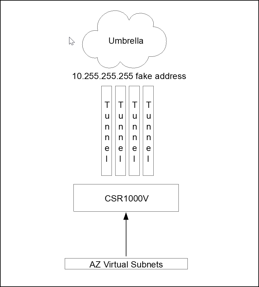
Four static routes to 10.255.255.255 address one per tunnel interface and route-map setting next-hop 10.255.255.255 fake address.
!
! *** Sample Access List with few possible match statements ***
!
ip access-list extended TRAFFIC_TO_UMB
 10 permit ip host 172.16.10.103 any
 20 permit ip any any
 30 permit tcp any any eq www
!
!
! *** Route-map matching the access list and setting 10.255.255.255 as recursive next-hop ***
!
route-map ROUTE_TO_UMBRELLA permit 10
 match ip address TRAFFIC_TO_UMB
 set ip next-hop recursive 10.255.255.255
!
!
! *** To get to 10.255.255.255 the traffic is load shared across the 4 tunnels (CEF) ***
!
ip route vrf INSIDE 10.255.255.255 255.255.255.255 Tunnel1
ip route vrf INSIDE 10.255.255.255 255.255.255.255 Tunnel2
ip route vrf INSIDE 10.255.255.255 255.255.255.255 Tunnel3
ip route vrf INSIDE 10.255.255.255 255.255.255.255 Tunnel4
!
!
! *** Route-map assigned to inside interface ***
!
interface GigabitEthernet2
 description **** INSIDE ****
 vrf forwarding INSIDE
 ip address 10.0.1.5 255.255.255.0
 ip policy route-map ROUTE_TO_UMBRELLA
!
Azure Virtual Network Routing to CSR1000V
After configuring the tunnel in CSR1000V, you must create a new routing table to ensure that the hosts traffic is forwarded through the virtual router. Azure has a default routing table that sets Internet as next hop for all subnets. Change this default route to the CSR1000V router by creating a new routing table.
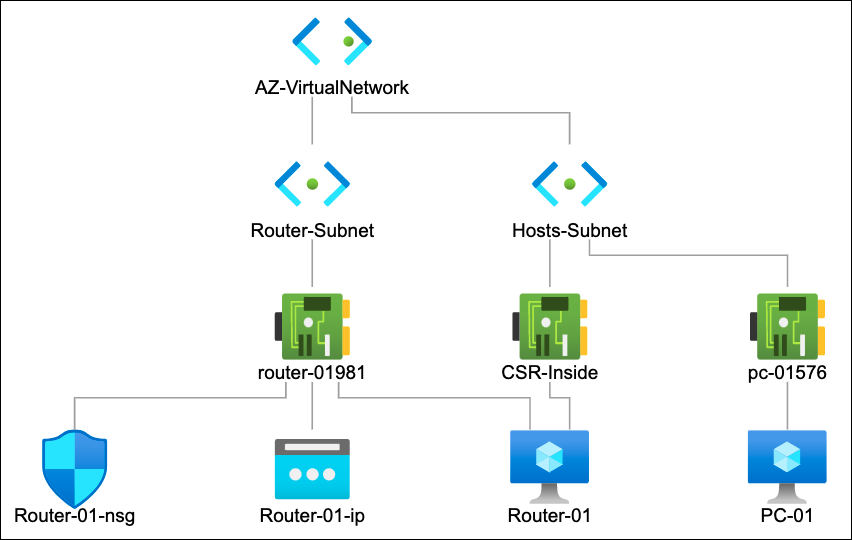
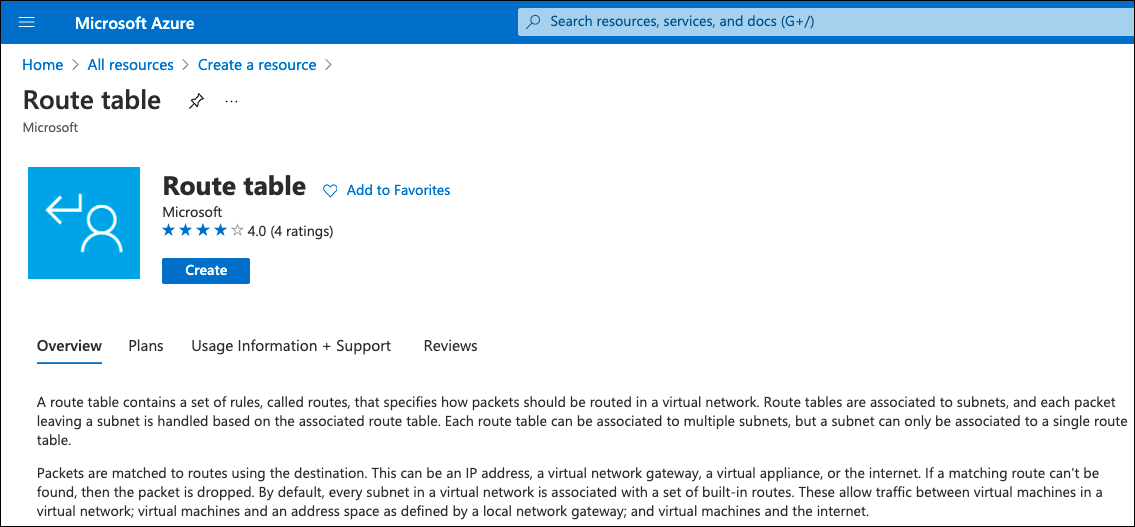
- Search for Route Table and create a new routing table.
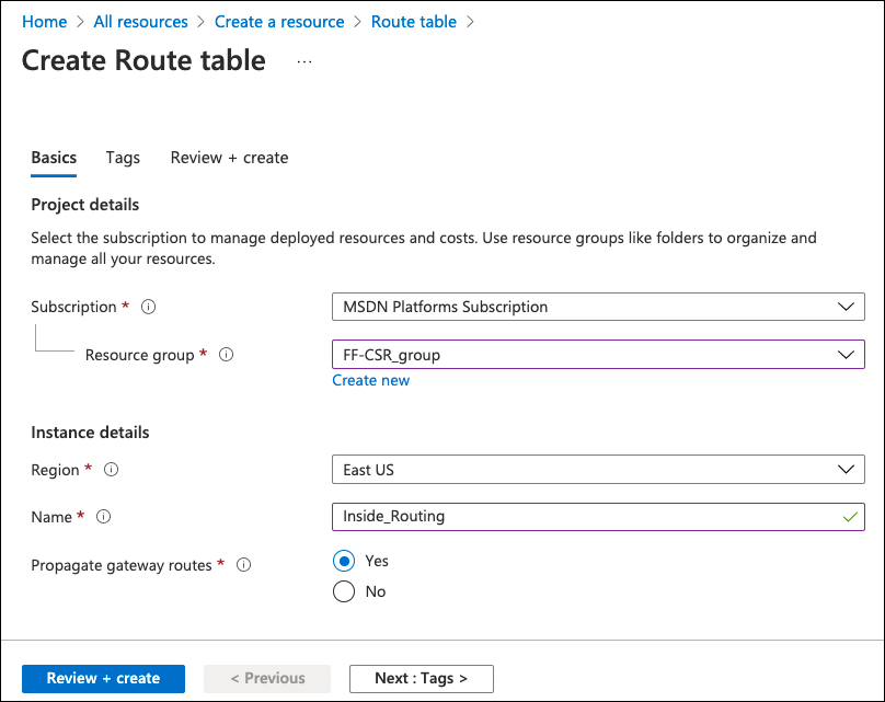
- Provide a name, select resource group, region and create.
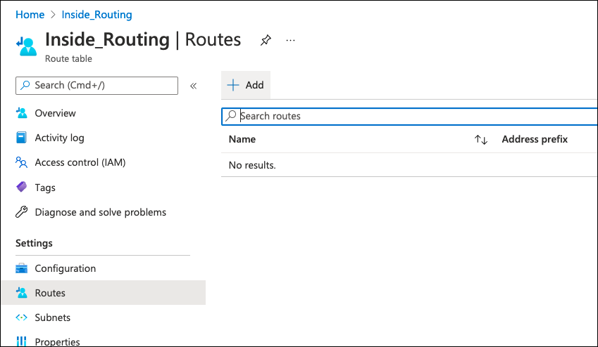
After the new route table is created, you can change it to include the custom routes.
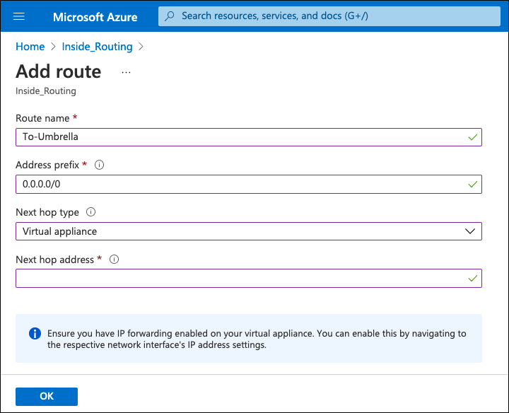
- Add new default route, select Virtual Appliance as next hop type, add the CSR1000V inside interface IP address, and click OK.
- Assign the route table to the subnet:
a. Navigate to the Azure virtual network, select Subnets and change the subnet the hosts reside on.
Note: Do not assign the new route table to the router’s internet facing subnet.
b. In the Route Table option, assign the just created route table and click Save.
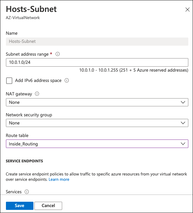
All hosts in the subnet now default route to the CSR1000V router and access the internet through Umbrella.
- Provide a name, select resource group, region and create.
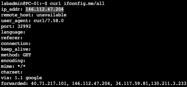
CSR1000V Umbrella Configuration
IOS-XE devices, including CSR1000V, authenticate to the Umbrella IPsec headend through a pre-shared key (PSK) and IKEv2 FQDN identity.
- In the Umbrella dashboard navigate to Deployments > Core Identities > Network Tunnels and click Add.
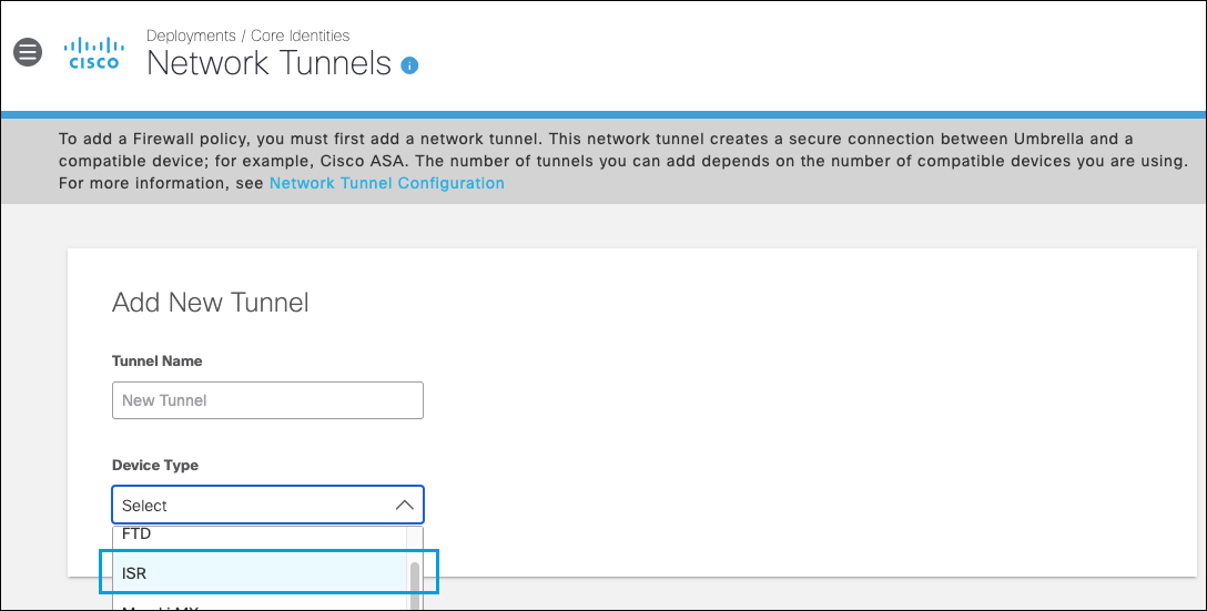
Note: Add a tunnel based on the ISR template. - Provide a tunnel name, choose ISR as the device type and save.
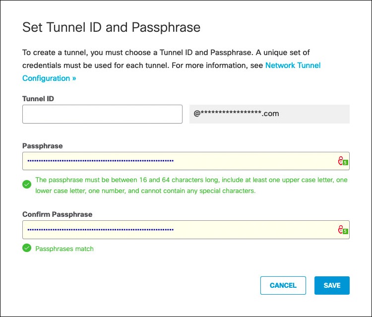
- Under tunnel ID type a unique tunnel identity (not yet in use by other tunnels), provide a pre-shared key between 16 and 64 characters (the one to be used in CSR1000V VPN configuration) and click Save.
Note: Tunnel status is Not Established until the first IKEv2 INIT message containing the tunnel identity is seen in one of the Umbrella data centers.
Equal Cost Multi-Path Routing
For Equal-cost multi-path routing (ECMP)— traffic load sharing across multiple tunnels—repeat the steps above and create as many tunnels as the number of tunnels configured in the CSR1000V.
Troubleshoot the CSR1000V VPN
The first step to identify a tunnel issue is to confirm if the tunnel is up.
- If the status is
down, then the tunnel is shutdown. Under the tunnel interface type no shutdown. - If the protocol is
down, then the IKEv2 session failed to negotiate.
For more information about troubleshooting the IKE session, see IOS IKEv2 Debugs for Site-to-Site VPN with PSKs Troubleshooting TechNote.
show ip interface brief
The output is similar to:
Interface              IP-Address      OK? Method Status                Protocol
GigabitEthernet1       10.0.0.4        YES DHCP   up                    up
GigabitEthernet2       10.0.1.5        YES manual up                    up
Loopback1              192.168.0.1     YES manual up                    up
Loopback2              192.168.0.2     YES manual up                    up
Loopback3              192.168.0.3     YES manual up                    up
Loopback4              192.168.0.4     YES manual up                    up
Tunnel1                192.168.0.1     YES TFTP   up                    up
Tunnel2                192.168.0.2     YES TFTP   up                    up
Tunnel3                192.168.0.3     YES TFTP   up                    up
Tunnel4                192.168.0.4     YES TFTP   up                    up
VirtualPortGroup0      192.168.35.101  YES NVRAM  up                    up
Other Resources
Azure site to site VPN configuration guide
Umbrella Cloud Firewall
Cisco Cloud Services Router (CSR) 1000V
- Cisco CSR 1000v Deployment Guide for Microsoft Azure
- IOS IKEv2 Debugs for Site-to-Site VPN with PSKs Troubleshooting TechNote
Configure Tunnels with Cisco Router in AWS < Configure Tunnels with Azure IPsec > Configure Tunnels with Oracle Cloud IPsec
Updated about 1 year ago
