Configure Tunnels with Oracle Cloud IPsec
Oracle Cloud Infrastructure (OCI) offers multiple options for setting up an IPsec Tunnel between OCI Virtual Cloud Networks and Cisco Umbrella. This guide focuses on Oracle Cloud Site-to-Site VPN and Cisco Adaptive Security Appliance Virtual (ASAv).
Table of Contents
- Configure Oracle Cloud Tunnels with Umbrella
- Configure Multiple Isolated OCI VPNs
- Configure Multiple OCI VPNs with Local Peering Gateway
Configure Oracle Cloud Interface Tunnels with Umbrella
You must configure the OCI side of the tunnels instance first, as you will need the IP addresses from OCI to configure the Umbrella side. This will work best if you access your OCI instances by private IP through an existing tunnel. If you access your OCI instances through the public IP address assigned by OCI, you will need to add exceptions for the IP ranges you will be accessing those instances from.
Note: The guide expects that you already have a VCN setup in the OCI dashboard. If not, please create a VCN that you would like sent over the Umbrella IPsec Tunnel.
Configure the Customer-Premises Equipment
First, configure which Umbrella Datacenter want OCI to connect to.
- Login to the OCI dashboard and navigate to Networking > Virtual Cloud Networks.
- Click Customer Connectivity > Customer-Premises Equipment and then click Create Customer-Premises Equipment.
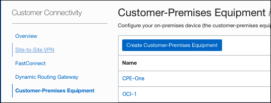
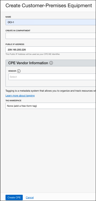
- Provide a meaningful name and the compartment you want this customer-premises equipment (CPE) created in. The compartment should be the same as where the VCN where you will route to Umbrella is located.
- Choose a Cisco Umbrella data center to connect to and enter the IP address. We recommend using the data center closest to your location.
- From the Vendor drop-down menu choose Other, optionally add any tags, and click Create CPE.
Configure Site-to-site VPN
- In the OCI dashboard, navigate to Customer Connectivity > Site-to-Site VPN and click Create IPSec Connection.
- Provide a name and choose a compartment (VPN) for the tunnel.
- Choose the Customer-Premises Equipment created previously and choose a Dynamic Routing Gateway.
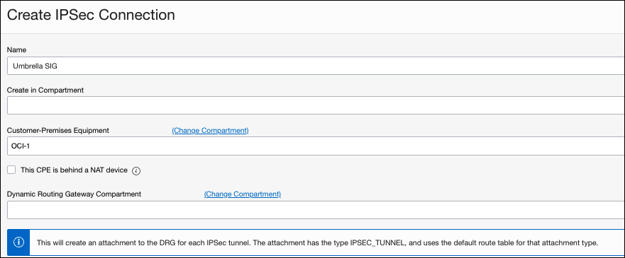
- For Routes to your On-Premise Network, enter 0.0.0.0/0.
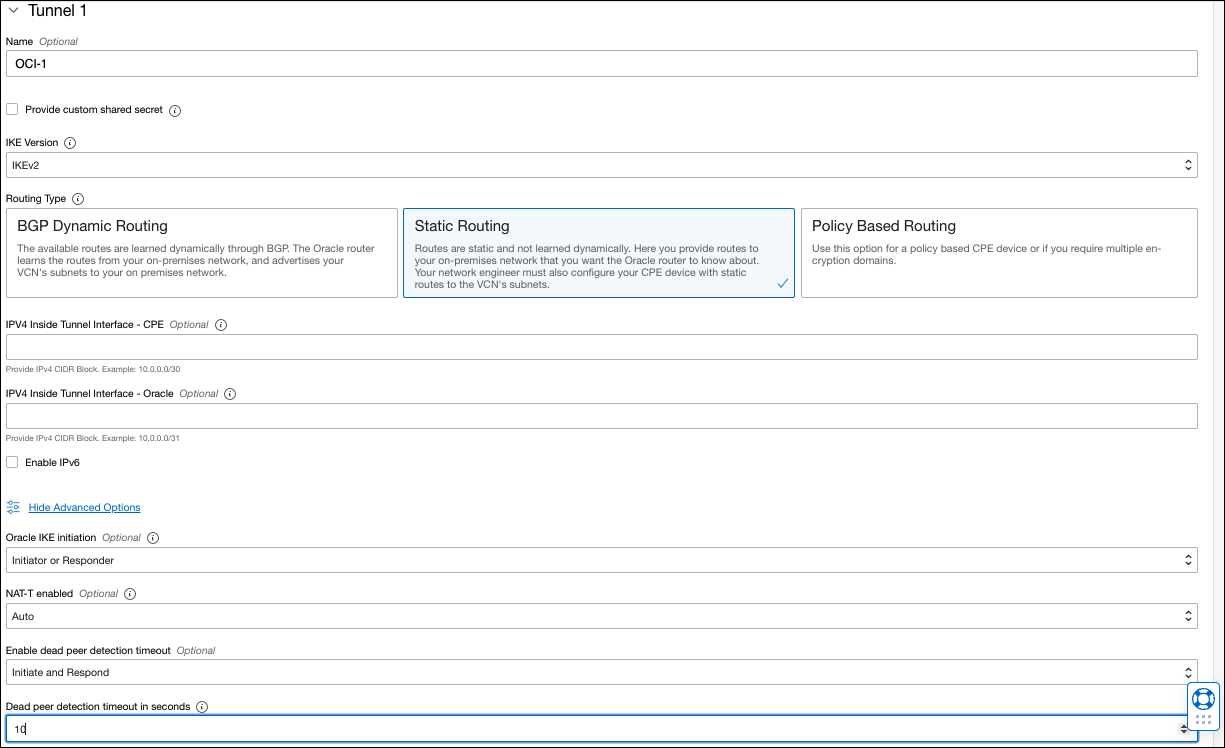
- Provide a meaningful name for the tunnel.
- Check the box for Provide custom shared secret. The secret must be between 16 and 64 characters with at least one upper case letter, one lower case letter, and one number. It can not contain any special characters.
Note: You will need this secret later for configuring Umbrella. - Click Advanced Options, check the box for Set Custom Configuration for both Phase 1 and Phase 2, and enter the following information:
- IKE Version—IKEv2
- Route Type—Static Routing
- IPv4 Inside Tunnel CPE:—(optional) See the Oracle tool tip for more information.
- IPv4 Inside Tunnel Oracle—(optional) See the Oracle tool tip for more information.
- Oracle IKE initiation—(optional) the default is Initiate or Respond
- NAT-T enables—(optional) the default is auto
- Dead peer detection timeout—10 seconds
Note: You can choose to use Policy-based routing (PBR), however, Umbrella does not support BGP dynamic routing for SIG tunnels.
a. Configure the following for Phase 1:
- Custom Encryption Algorithm—AES_256_GCM
- Custom Authentication Algorithm—SHA2_256
- Custom Diffie-Hellman Group—GROUP14
- IKE Session Key Lifetime—28800

b. Configure the following for Phase 2.
- Custom Encryption Algorithm—AES_256_GCM
- Custom Authentication Algorithm—HMAC_SHA1_28
- IKE Session Key Lifetime—3600

- Repeat steps 5-7 fo your second tunnel and click Create IPSec Connection.
- Collect the public IP addresses for each tunnel.
a. Navigate to Networking > Customer Connectivity > Site-to-Site VPN and click on one of the newly created tunnels.
b. Note the IP addresses under Oracle VPN IP Address for each tunnel.
Configure Umbrella Network Tunnels
- Login to the Cisco Umbrella dashboard, navigate to Deployments > Core Identities > Network Tunnels, and click Add.
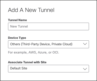
- Provide a name for the tunnel, choose Other (Third-Party Device, Private Cloud) for device, and optionally choose a Site to tie to the tunnel.
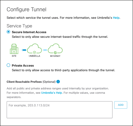
- Select Secure Internet Access for the Service Type.
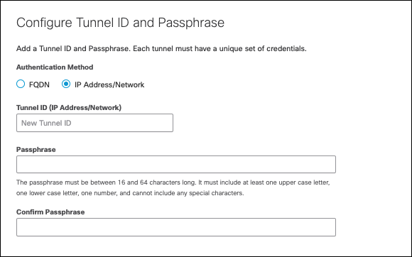
- Select IP Address/Network for Authentication Method, enter in the tunnel IP from step 9 of Configure Umbrella Network Tunnels, and the passphrase from step 6 of Configure Umbrella Network Tunnels. Click Save.
- Repeat steps 1-4 for the second tunnel.
Configure Routes
In order to send traffic down the tunnel, you need to tell your VCN to send internet bound traffic down the tunnel. You also need to add routes to ensure management connectivity to your OCI instances if you access them over the direct internet. If you are access OCI instances over the internet, then you need to add some routes to ensure that management traffic still goes over the OCI Internet Gateway, instead of Umbrella's SIG.
Configure Customer Routes
- In the OCI dashboard, navigate to Networking > Virtual Cloud Networks and click the name of your VCN.
- Choose Route Tables, click the name of the route table you want to modify, and click Add Route Rules.
- Configure the following fields:
- Target Type—Internet Gateway
- Destination CIDR Block—your IP range
- Target Internet Gateway—internet gateway for this VNC
- Description—description of the rule
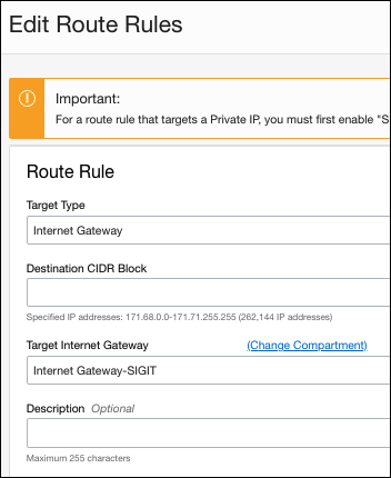
- Click Save Changes and repeat for any other IP ranges.
Configure Umbrella Routes
- In the OCI dashboard, navigate to Networking > Virtual Cloud Networks and click the name of your VCN.
- Choose Route Tables, click the name of the route table you want to modify, and click Add Route Rules.
- Configure the following fields:
- Target Type—Dynamic Routing Gateway
- Destination CIDR Block—0.0.0.0/0
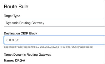
Note: The name of the dynamic routing gateway (DRG) will always be the DRG for this VCN.
- Click Save Changes.
<a name"verify">
Verify the Configuration
You can verify the tunnel configuration in three ways:
- A curl command
You should see your egress IP Address as something in the 146.112.x.x, 151.186.x.x, or 155.190.x.x range.
For example:
ubuntu@ubuntu-sig-oci-1:~$curl ifconfig.me
- The Umbrella Dashboard:
Navigate to Deployments > Core Identities > Network Tunnels.

- The Oracle Dashboard:

Configure Multiple Isolated OCI VPNs
The recommended method for tunnels to Umbrella would be with an ASAv. This allows the ASA to act as a router on a stick to easily direct internet-based traffic to Umbrella. This also allows easier routing from different VCNs to Umbrella as opposed to the native OCI Tunnels.
Deploy the Cisco ASAv
- Navigate to the Oracle Marketplace > Partner Images and search for Cisco ASA Virtual.
- Deploy the image with the following configuration:
- Name—provide a name for the ASAv
- Placement (Availability domain)—
- Image—Cisco ASA Virtual firewall (ASAv)
- Shape—Minimum must be VM.Standard2.4
- Primary Network—select the VCN you want the ASAv to reside in
- Subnet—select the VCN subnet the ASAv interface should sit on
- Public IP Address—your public IP address used for management. It is recommended to keep this internally accessible only. If public, be sure to restrict SSH and HTTS to trusted public ranges.
- SSH Keys—add your SSH keys to access the appliance
- Boot Volume—default
- Click Create.
Configure Umbrella Network Tunnels
- Login to the Cisco Umbrella dashboard, navigate to Deployments > Core Identities > Network Tunnels, and click Add.
- Provide a name for the tunnel, choose Other (Third-Party Device, Private Cloud) for device, and optionally choose a Site to tie to the tunnel.

- Select Secure Internet Access for the Service Type.

- Select FQDN for Authentication Method, enter a descriptive Tunnel ID, and create a Passphrase.
Note: Save the passphrase in case you need to recreate the tunnels later.
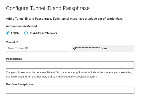
- Click Save and repeat steps 1-4 for any more tunnels.
Configure the Cisco ASAv
- SSH to the appliance with the username "admin" and your private key.
- Configure the IKEv2 policy as follows; see Supported IPsec Parameters for more information:
crypto ikev2 policy 10
	encryption aes-gcm-256
  integrity null
  group 19
  lifetime seconds 86400
Note: Replace the default device name "outside" with the name configured on your device. The ASA will only act as a router on a stick, we only need a single interface. The device name refers to the public facing interface which the VPN uses to connect.
- Configure the Group Policy and Tunnel Group parameters as follows:
group-policy umbrella-policy internal
group-policy umbrella-policy attributes
   vpn-tunnel-protocol ikev2

tunnel-group <umbrella_dc_ip> type ipsec-l2l
tunnel-group <umbrella_dc_ip> general-attributes
  default-group-policy umbrella-policy
tunnel-group <umbrella_dc_ip> ipsec-attributes
  ikev2 remote-authentication pre-shared-key 0 [Portal_Tunnel_Passphrase]
  ikev2 local-authentication pre-shared-key 0 [Portal_Tunnel_Passphrase]
- umbrella_dc_ip—your closest Umbrella SIG data center
- Portal_Tunnel_Passphrase—the passphrase previously created in Configure Umbrella Network Tunnels.
- Configure the IPsec proposal and profile parameters as follows; see Supported IPsec Parameters for more information:
crypto ipsec ikev2 ipsec-proposal Umbrella-Ipsec-Proposal
  protocol esp encryption aes-gcm-256
  protocol esp integrity sha-1

crypto ipsec profile Umbrella
  set ikev2 ipsec-proposal Umbrella-Ipsec-Proposal
  set ikev2 local-identity email-id [email protected]
- Create a VTI as follows:
interface Tunnel1
   nameif vti
   ip address 10.60.0.1 255.255.255.252 **//Sample IP**
   tunnel source interface management
   tunnel destination<umbrella_dc_ip>
   tunnel mode ipsec ipv4
   tunnel protection ipsec profile umbrella
- umbrella_dc_ip—your closest Umbrella SIG data center
- Sample IP—use a non-existing IP address that is not being used for a VLAN, subnet, or existing VLAN connection in your network.
- Configure policy-based routing as follows:
- Configure PBR to send the internal traffic through the tunnel interface to reach the Umbrella Data Center.
- Set the IP address in next-hop to the same subnet assigned to the VTI.
access-list ACL-Umbrella line 1 extended permit ip 10.30.1.0 255.255.255.0 any4

route-map Umbrella-PBR permit 10
  match ip address ACL-Umbrella
  set ip next-hop 10.60.0.2 **Note that this is in the same /30 subnet as the Tunnel interface ip address**

interface management
  policy-route route-map Umbrella-PBR
Note: This example uses 10.30.1.0/24 for the LAN subnet and management for the LAN interface.
Route Traffic through the ASAv
- Navigate to the VCN you want to route through the ASAv, navigate to Route Tables and select the route table used for this VCN.
- Click Add Route Rules and configure the following:
- Target Type—Private IP
- Destination Type—CIDR Block
- Destination CIDR Block—0.0.0.0/0
- Target Selection—the IP address of the ASAv interface
- Click Add Route Rules to save.
Verify the Configuration
You can verify the tunnel configuration in three ways:
- A curl command
You should see your egress IP Address as something in the 146.112.x.x, 151.186.x.x, or 155.190.x.x range.
For example:
ubuntu@ubuntuasav:~$ curl ifconfig.me
- The Umbrella Dashboard
Navigate to Deployments > Core Identities > Network Tunnels. - The ASAv command-line interface (CLI)
Run the following commands:
show crypto ikev2 sa detail
show crypto ipsec sa detail
Configure Multiple OCI VPNs with Local Peering Gateway
If you have multiple VCNs, you can configure Local Peering Gateways to provide interconnectivity between VCNs.
Configure the Transit VCN
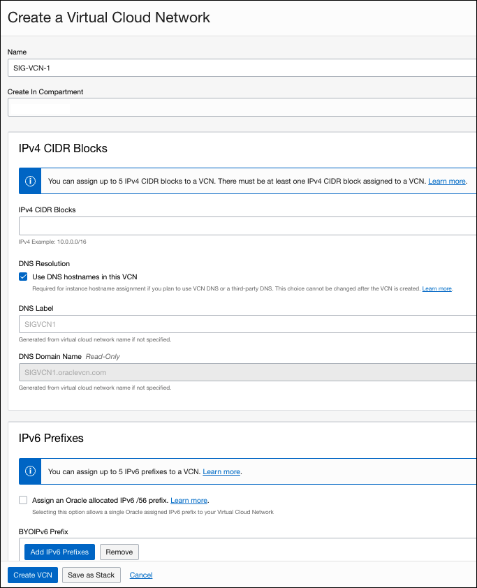
- In the OCI dashboard, navigate to Networking > Virtual Cloud Networks > Create VCN and provide a name for the VCN.
- Create a new IPv4 CIDR block. The block cannot overlap with any existing subnet.
- Click Subnets > Create Subnet and provide a name.
- Provide the same IPv4 CIDR block as step 2, choose Private Sennet and click Create Subnet.
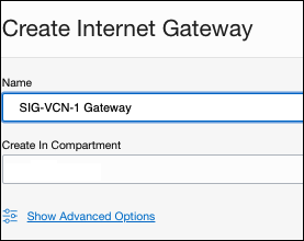
- Navigate to Networking > Virtual Cloud Networks > [VCN Name] > Internet Gateways > Create Internet Gateway.
- Provide a name and click Create Internet Gateway.
Route Rules for VPN Traffic to Umbrella Data Center
- In the OCI dashboard, navigate to Networking > Virtual Cloud Networks > [VCN Name] > Route Tables > Default Route Table for [VCN Name] and click Add Route Rules.
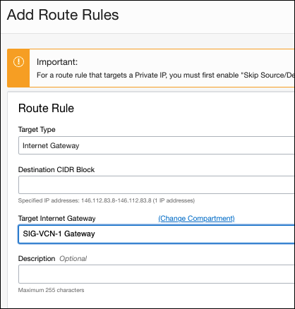
- Add the Umbrella IPsec head-end for the Destination CIDR Block and choose Internet Gateway for Target Type. Then click Add Route Rules.
- Deploy the Cisco ASAv
- Configure Umbrella Network Tunnels
- Configure the Cisco ASAv
Note: When you add the access list for which subnets you want to route the ASAv tunnel to Umbrella, be sure to add the subnets for your other VCNs as well.
Connect the Local Peering Gateway
- In the OCI dashboard, navigate to Networking > [VCN Name] > Local Peering Gateways and click Create Local Peering Gateway.
- Provide a name (for example, Peer Gateway 1) and click Create Local Peering Gateway.
- Navigate to the [VCN to peer with] > Local Peering Gateways and click Create Local Peering Gateway.
- Provide a name (such as Peer Gateway 2) and click Create Local Peering Gateway.
The gateway appears as Available with a Peering Status of New - Not connected to a peer.

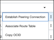
- Click the action menu next to the newly created Local Peering Gateway (Peer Gateway 2) and click Establish Peering Connection.
- From the Virtual Cloud Network drop-down, choose [VCN Name].
- Choose the Local Peering Gateway created in step 2 (Peer Gateway 1) and click Establish Peering Connection.
The Peering Status changes to Pending and then Peered - Connected to a peer. The subnets will also populate in the Peer Advertised CIDRs.

- Navigate to [VCN Name] > Local Peering Gateways to view the updated status for the other gateway and the Peer Advertised CIDRs.

Route Rules through Local Peering Gateway for Other VCNs
You need to add some static routes to route traffic from your other VCN’s to the ASAv VCN.
- Navigate to the [VCN you peered with] > Route Tables, choose the route table and click Add Route Rules.
- Configure the following fields:
- Target Type—Local Peering Gateway
- Destination CIDR Block—0.0.0.0/0
- Target Local Peering Gateway—your VCN name
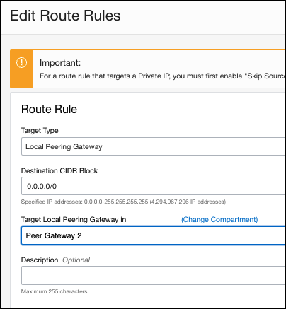
- Click Add Route Rules and repeat steps 1-2 for any other VCNs to route through the ASAv.
Verify the Configuration
Verify the tunnel configuration with the following curl command:
ubuntu@ubuntuasav:~$ curl ifconfig
You should see your egress IP Address as something in the 146.112.x.x, 151.186.x.x, or 155.190.x.x range.
Configure Tunnels with Azure IPsec < Configure Tunnels with Oracle Cloud IPsec > Configure Tunnels with Google Cloud Platform IPsec
Updated almost 2 years ago
