
Configure Tunnels with Checkpoint GAiA
The content provided here explains how you can configure an IPsec tunnel between a Checkpoint Firewall and Umbrella. The objective is to protect devices behind the Checkpoint Firewall by sending their web traffic to Umbrella through a route-based IPsec tunnel.
Note
This document is based on Checkpoint Firewall version R81.10. While IPsec tunnels will continue to work with updated devices, connectivity cannot be guaranteed for versions not explicitly listed as tested.
Table of Contents
<a name="prerequisites>
Prerequisites
The following prerequisites must be met for the tunnel to work.
Licensing and Hardware
- Presence of a checkpoint gateway with VPN blade enabled
- Presence of a checkpoint gateway with software R80.30 or above
- A valid Umbrella SIG Essentials or SIG Advantage license
Network Access
Select an Umbrella SIG Data Center IP address that you can use when creating the IPsec tunnel. Cisco recommends choosing the IP address based on the data center located closest to you.
UDP ports 500 and 4500 must be opened before connecting to the tunnel.
Checkpoint Gateway requires a public IPv4 address to be configured on the interface that will connect to the internet. This IPv4 address must be used as IKE identity.
Configure Tunnels in Umbrella
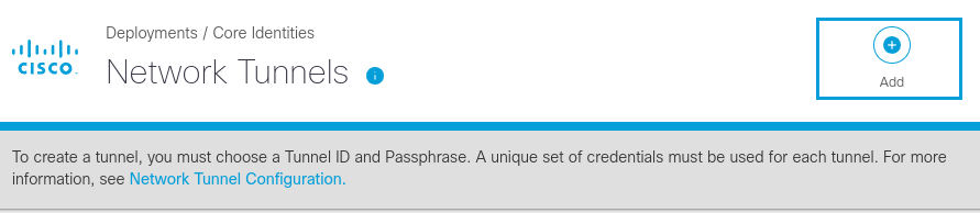
- Navigate to Deployments > Core Identities > Network Tunnels, then click Add
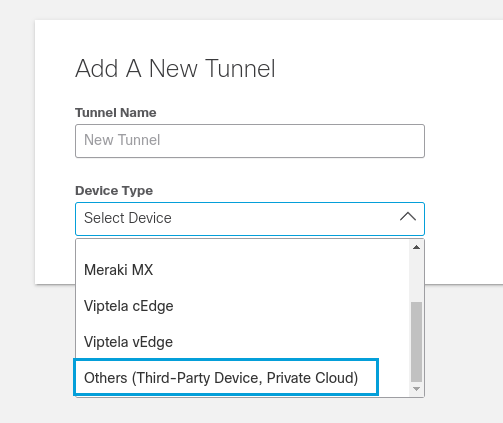
- Give your tunnel a meaningful name. From the Device Type drop-down list choose Other. Choose the Umbrella site for the new tunnel. Click Save.
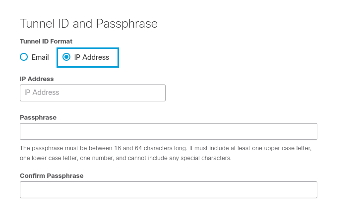
- Select IP Address as the Tunnel ID format. Enter the Tunnel ID, which should be a valid public IP address. Enter your Pre-Shared- Key (PSK) in the Passphrase and Confirm Passphrase fields. Click Save.
Configure Checkpoint Gateway Firewall
Add Interoperable Device
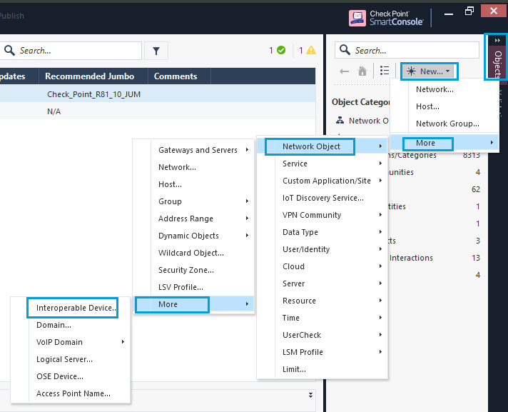
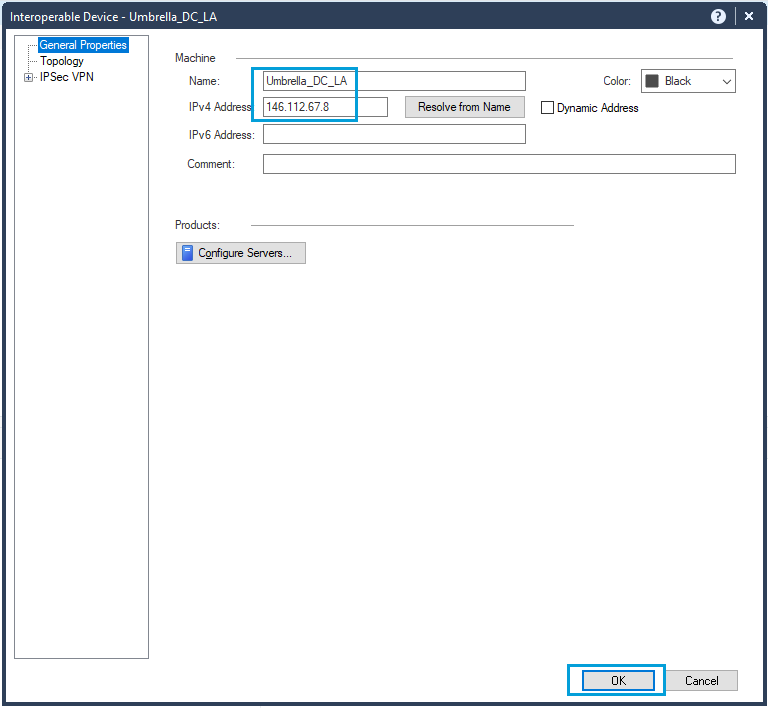
- In SmartConsole, go to Objects. Click New > More > Network Object > More and select Interoperable device object. This type of object is used in VPN communities when establishing tunnels with non-checkpoint devices. We need to register an Umbrella Data Center IP inside this object.
- Provide a meaningful name to the interoperable device. Add an IP address from the nearest Umbrella SIG data center. Click OK to save the changes.
Configure Network Group Object for Interesting Traffic
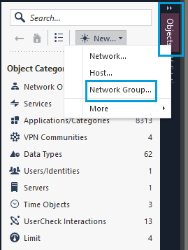
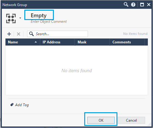
- In the Objects pane, click New, and select Network Group as the object type. The Network Group object is used for interesting traffic. Give the object a name and leave it blank. Click OK to save the changes.
Given here is the screenshot of an object named Empty.
Create VPN Community
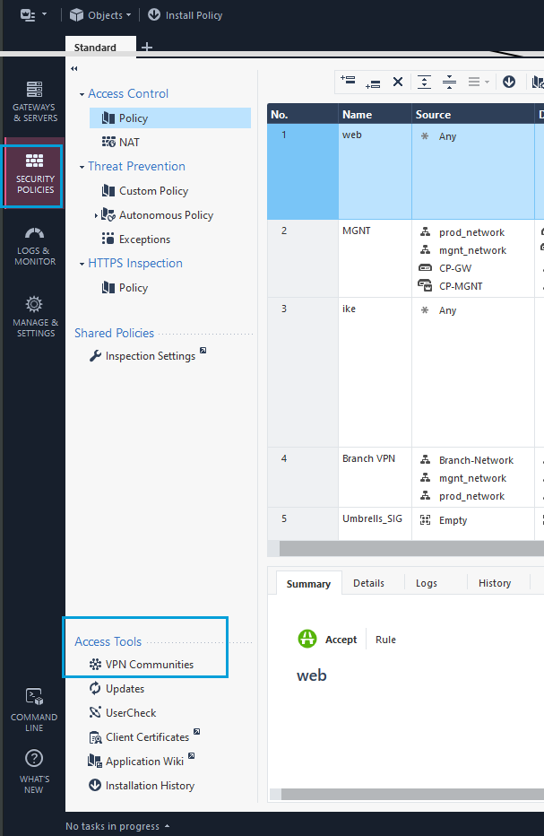
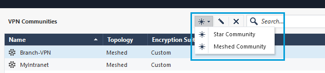
- In the SmartConsole, go to Security Policies, Access Tools. Click VPN Communities > Add a New Community. You can create Meshed or Star communities. The screenshot given here shows the configuration of a meshed community.
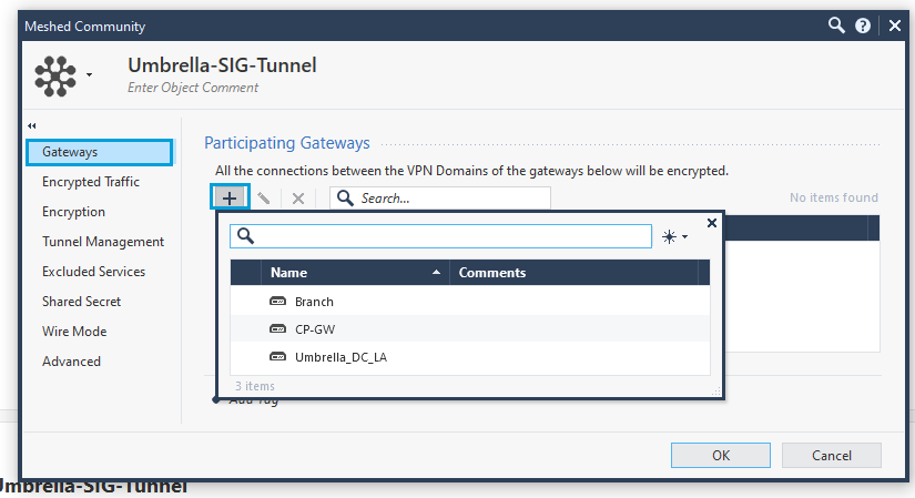
- In the VPN Communities window, under Gateways > Participating Gateways, add the local Gateway and the Interoperable Device created in Step 1. If you hover over the list of devices a + sign appears on the left-most column. Click the + sign to add the local Gateway and the Umbrella Interoperable Device.
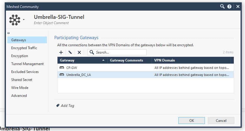
Once the Gateway and the Interoperable Device are added, they show in the list.
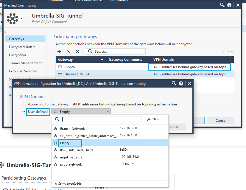
- Call the Network Group Object Empty, and add it to the Checkpoint and Umbrella Gateways. Double-click the VPN Domain column, click User-Defined, and select the object named Empty. Add it to both the Checkpoint Gateway and the Umbrella Gateway. In the screenshot given here, the object has been added to the Checkpoint Gateway (CP-GW).
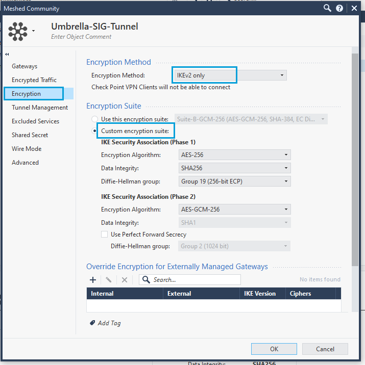
- Click Encryption to configure the IPsec tunnel parameters. Select IKEv2 only as the Encryption Method and Custom Encryption suite as the Encryption Suite. Configure the parameters for both Phase 1 and Phase 2. Ensure that you use the Cisco recommended Umbrella IPsec supported parameters.
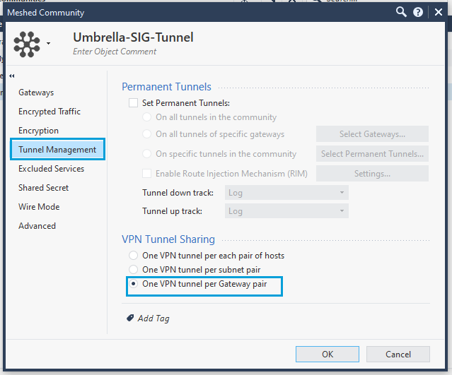
- Click Tunnel Management, and select One VPN Tunnel Per Gateway Pair as the VPN Tunnel Sharing option. Cisco data centers establish one child SA per tunnel and it is crucial that the Checkpoint is similarly configured.
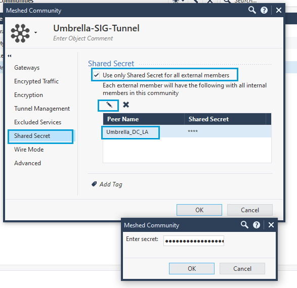
- Click Shared Secret. Select Use only Shared Secret for all external members. Select the Umbrella Interoperable object and select the Edit icon to add the Pre-Shared-Key (PSK). Enter the PSK that you configured as Tunnel Passphrase. Click OK.
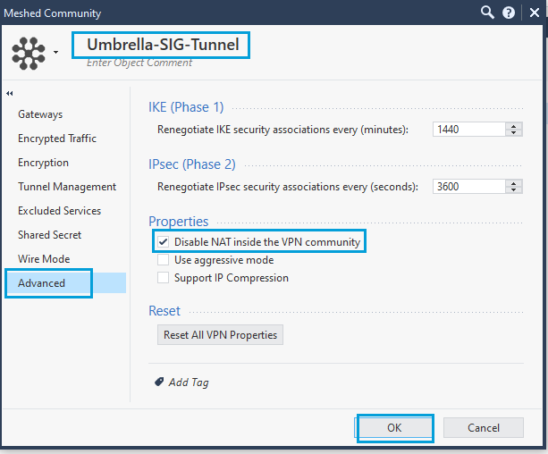
- In the Advanced menu, under Properties, select Disable NAT inside the VPN Community. Disabling NAT ensures that source IP address is conserved for all web traffic, which in turn provides you with the ability to enforce web policies based on source network, and also ensures granularity in the reports. Provide a meaningful name to the community (Umbrella-SIG-Tunnel in the screenshot).
Configure Security Policies
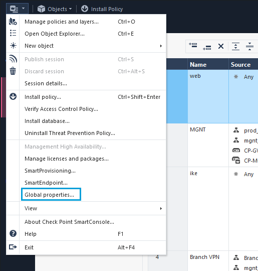
- Policies have to be configured to allow traffic through a Checkpoint firewall. Click Global Preferences.
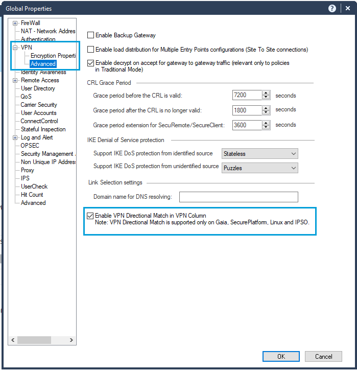
- Go to VPN > Advanced and select Enable VPN directional match in VPN column. Click OK. This setting is required when an Access Control policy is used in a route-based tunnel.
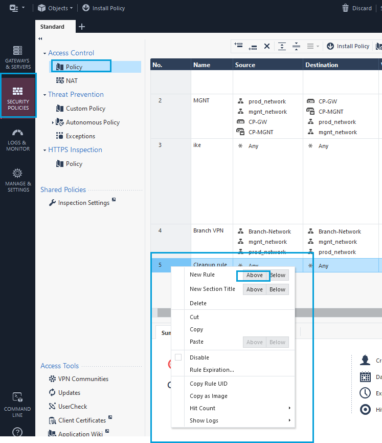
- Go to Security Policies > Access Tools. Click Policy to create a policy for the Umbrella Community or the configured VPN. This policy ensures that traffic from on-prem travels through the Umbrella tunnel. The policy should be above the cleanup rule because the SIG tunnel has interesting traffic set to any any. Right-click on the cleanup rule and add a rule above it.
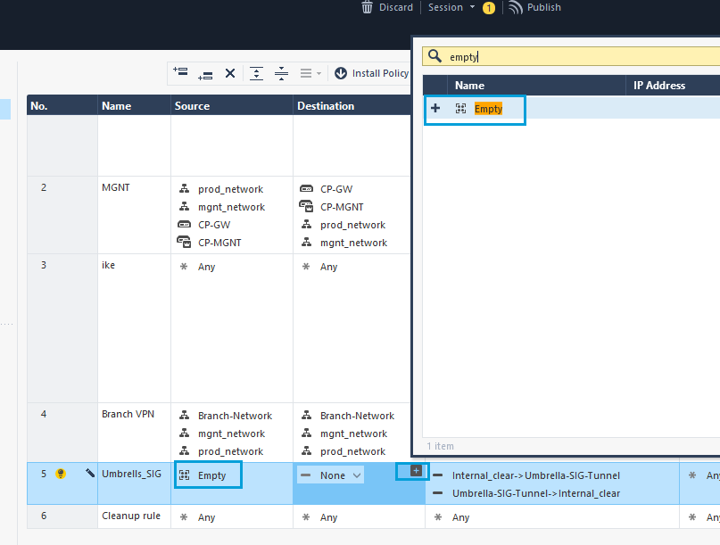
- In the newly-created policy, call the Network Group Object Empty. You can set the Network Group Object as both source and destination. Optionally, you can select a specific network in the source column, click the + icon to get the object search dialog box.
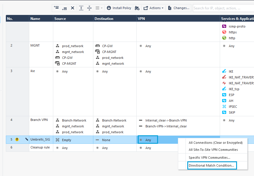
- Right-click in the VPN column and select Directional Match Condition.
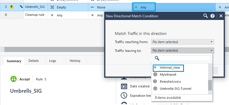
- For Traffic Reaching From, select Internal Clear (all traffic from internal domains). For Traffic Leaving To, select Umbrella Community.
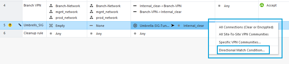
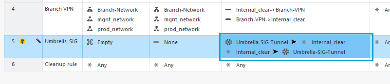
- Repeat these steps in the VPN column, but this time select the Umbrella Community first and the Internal Clear next.
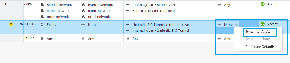
- In the Services & Applications column, select Switch to Any to allow unrestricted traffic to Umbrella.
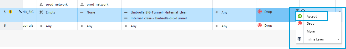
- Change Action to Accept.
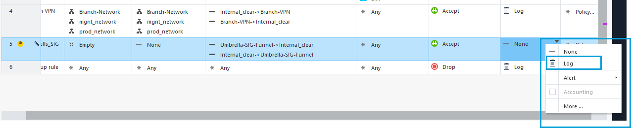
- In the Track column, select Log to view all the VPN connections in the log.
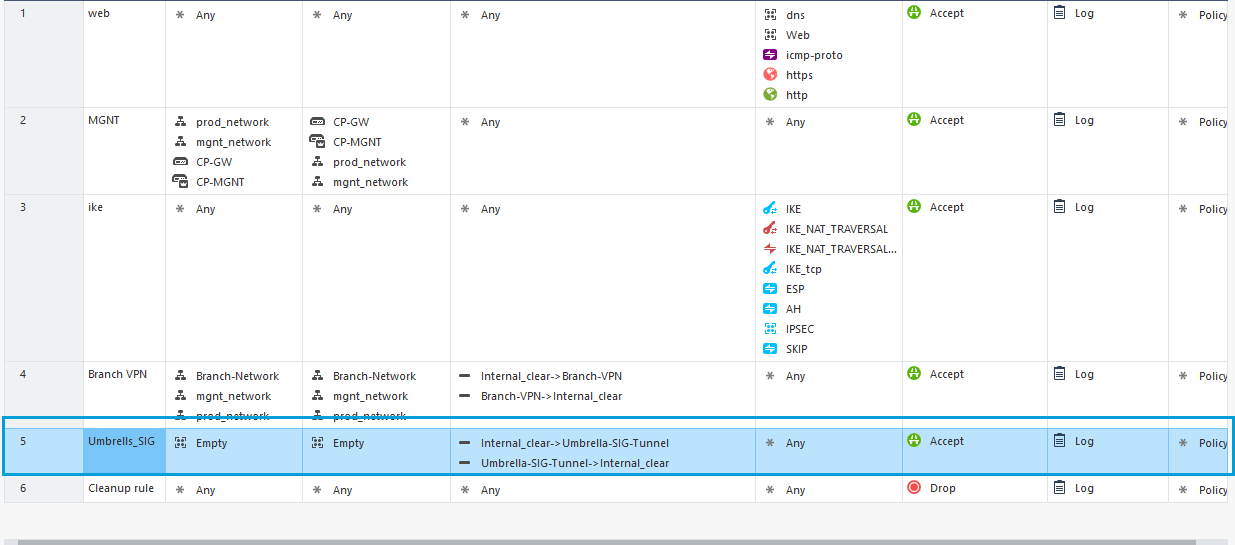
- Once you finish updating the values in all the columns, the result must be as shown in the screenshot.
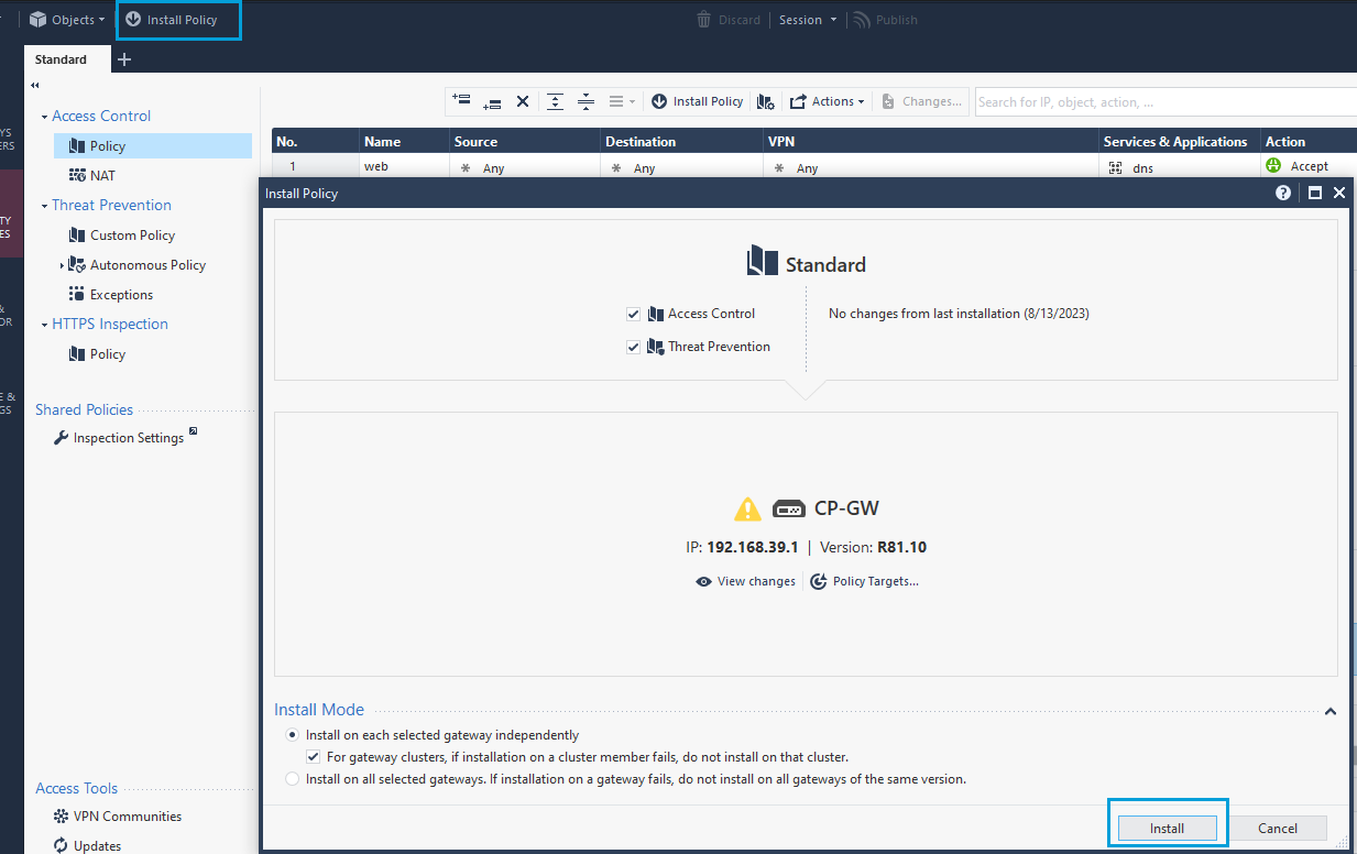
- Install the policy.
Configure VPN Tunnel Interface
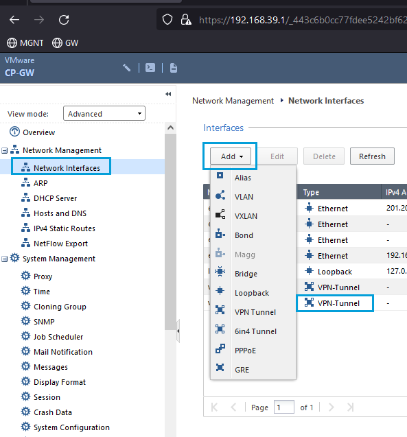
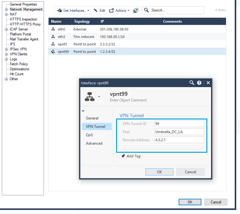
- Login to the WebUI of your Gateway using a web browser. Go to Network Interfaces. Override the lock, if required, to make configuration changes. Click Add > VPN Tunnel.
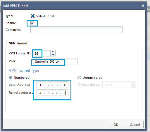
- Check the Enable checkbox. Enter any number as the VPN Tunnel ID. Enter the name of the Umbrella Interoperable object in the Peer field. Enter any IP address in the Local Address field. Enter any IP address in the Remote Address field. Both the local and remote address have only local significance. Click OK.
Note
If you are using routing protocols, you might need to specify IPs in a /30 subnet with two hosts. For example, for local and remote IP addresses within the same subnet with mask /30, the local IP address will be 10.10.10.1 and the remote IP address will be 10.10.10.2.
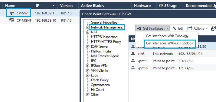
- To fetch the newly created interface from SmartConsole, double click Firewall, and go to Network Management > Get Interfaces > Get Interfaces Without Topology.
Note
If you fetch the interfaces with topology, you might need to reconfigure Spoofing settings for each interface.
- Ensure that the newly created tunnel interface was fetched correctly. Click OK to exit.
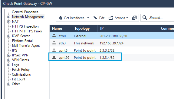
- Review the new set of interfaces.
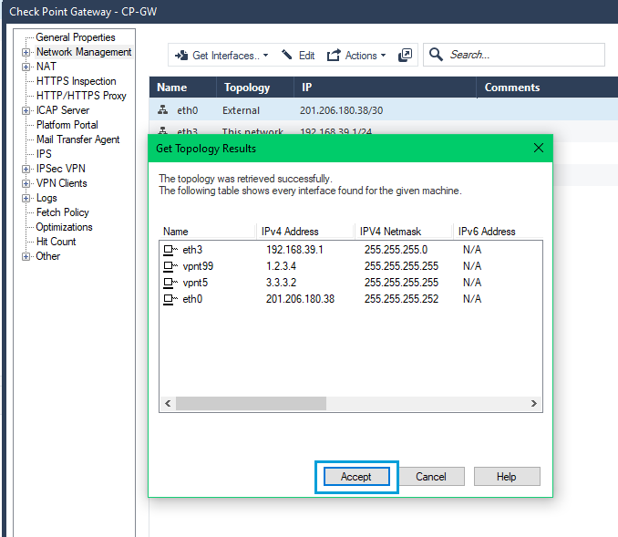
- The new topology table should also list the new tunnel interface.
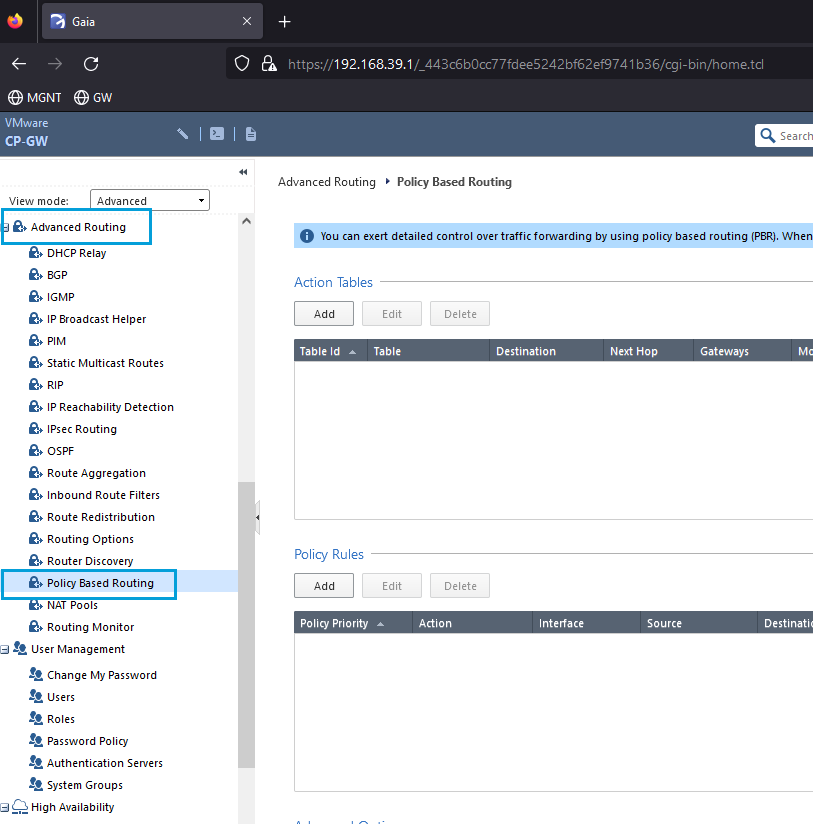
Configure Policy Based Routing
- In the WebGUI, go to Advanced Routing > Policy Based Routing. Use this option to configure a default route that will send all your traffic to the Umbrella Data Center through the tunnel.
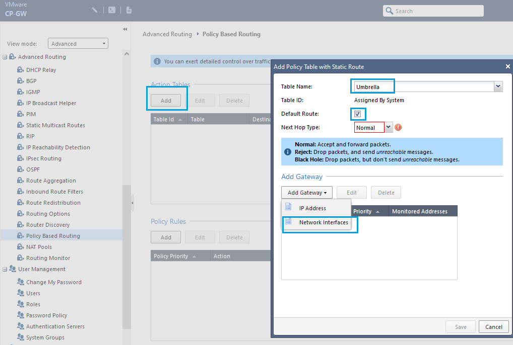
- Creating Policy Based Routing is a two-step process. First, you must create an Action Table that tells the gateway where to send the traffic. In the Action Table section, click Add to create a table for Umbrella. Enter a meaningful Table Name, check the Default Route checkbox, click Add Gateway, and select Network Interfaces.
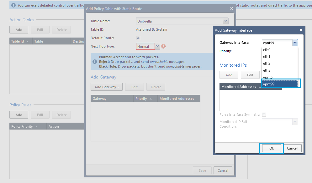
- Select VPN Interface that will be used for Umbrella SIG tunnel. Click OK and then Save.
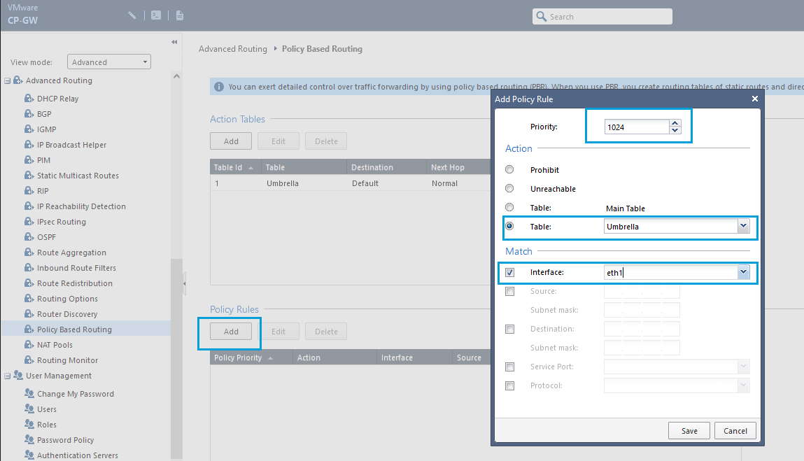
- The second step of Policy Based Routing is to configure the Policy Rules. Click Add and set Priority as 1024 (last priority). In the Action section, select the table created for Umbrella. In the Match section, check the Interface checkbox, and choose the interface where you want the policy to be applied. In general, the policy is applied to the interfaces that point to your internal network. Click Save.
Note
Create as many policy rules as required depending on the number of interfaces that point to your internal network in your Checkpoint Gateway. Always use the last available priority.
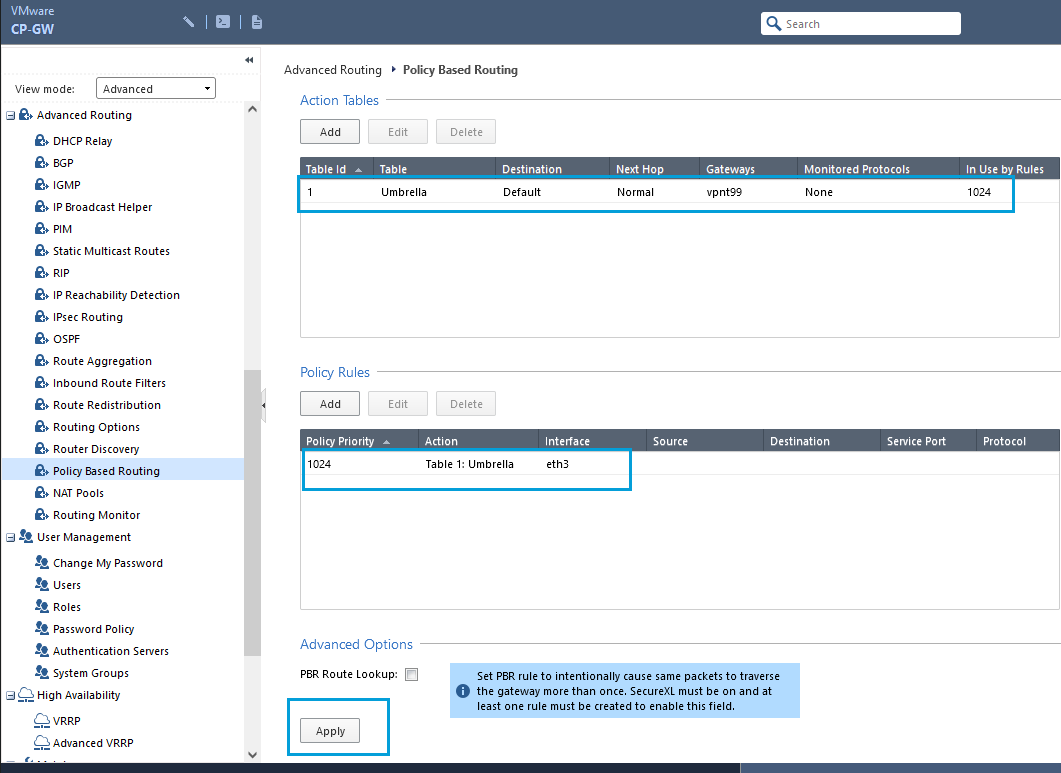
- Once the configuration is completed, you will get an output as shown in the screenshot. Click Apply to apply the configuration.
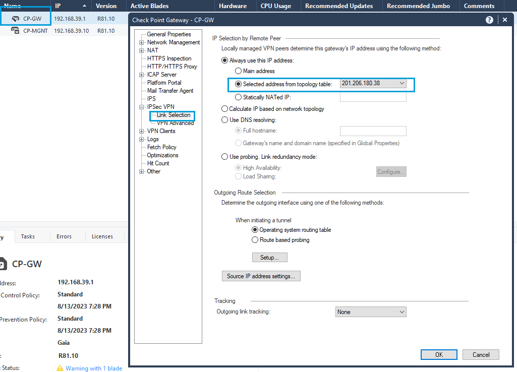
Provide IKE Identity
- By default, Checkpoint uses its management interface as identity. The management interface must be changed to the public IP. Go to Gateways & Servers, double-click the Firewall. Go to IPSec VPN > Link Selection. In IP Selection by Remote Peer > Selected address from Topology Table, select the Public IP address configured in the gateway (that is the IP address used as Tunnel ID while configuring the tunnel in the Umbrella Dashboard).
Note
This is a global change and the checkpoint uses the called interface as IKE identity for all your tunnels.
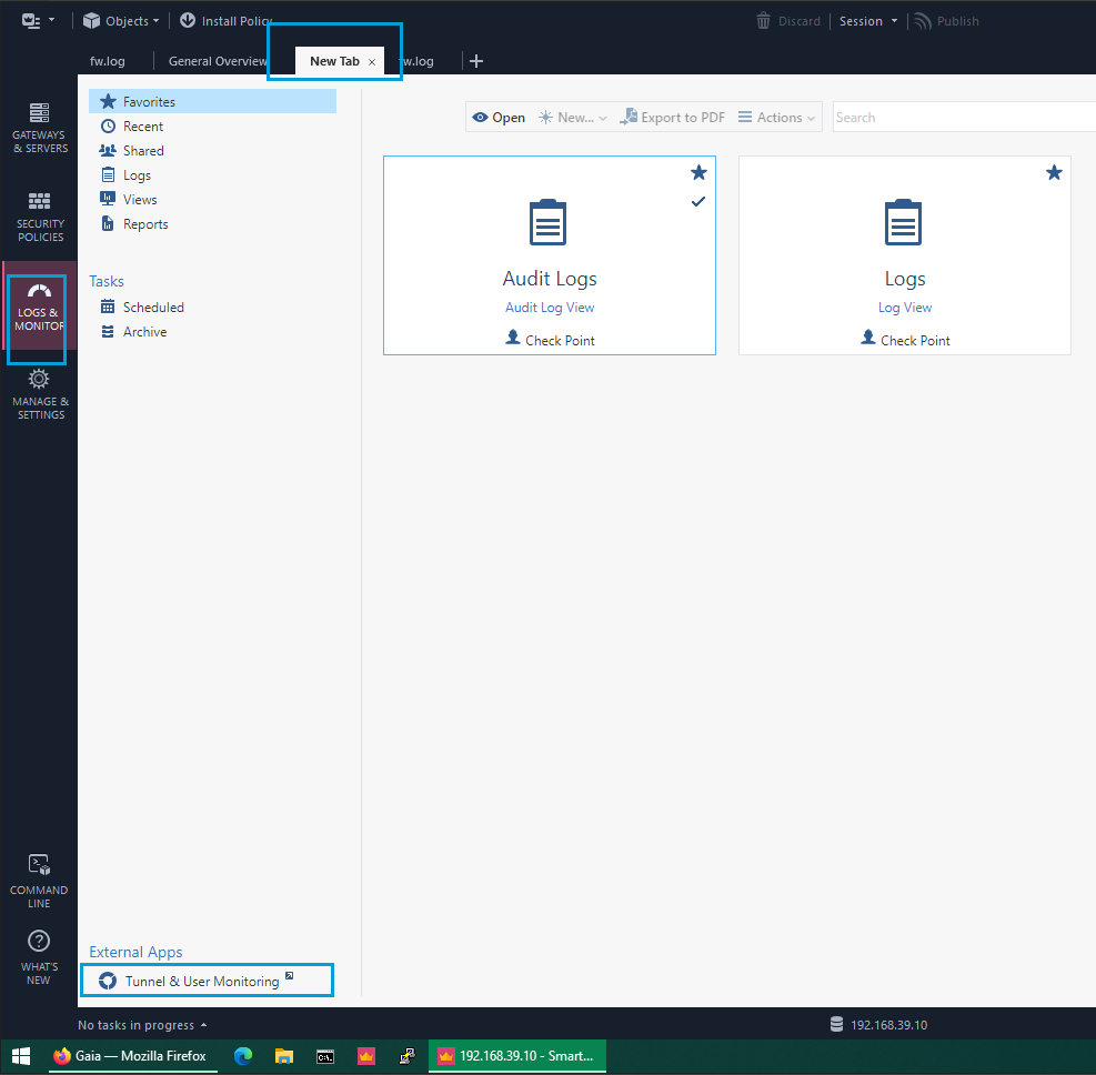
Verify Tunnel Status
- Go to Logs & Monitor, open a New Tab, and at the bottom, open Tunnel & User Monitoring.
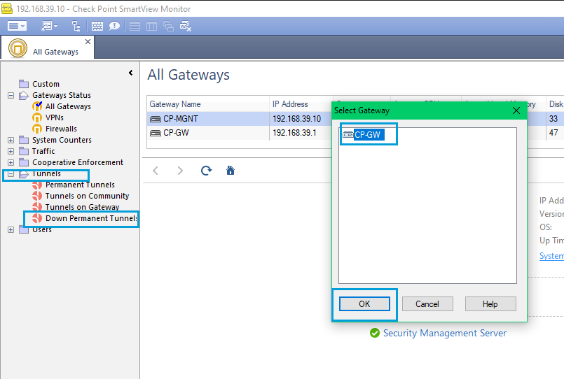
- In SmartView Monitor, open the Tunnels folder, select Tunnels on Gateway. Select your gateway in the popup and click OK.
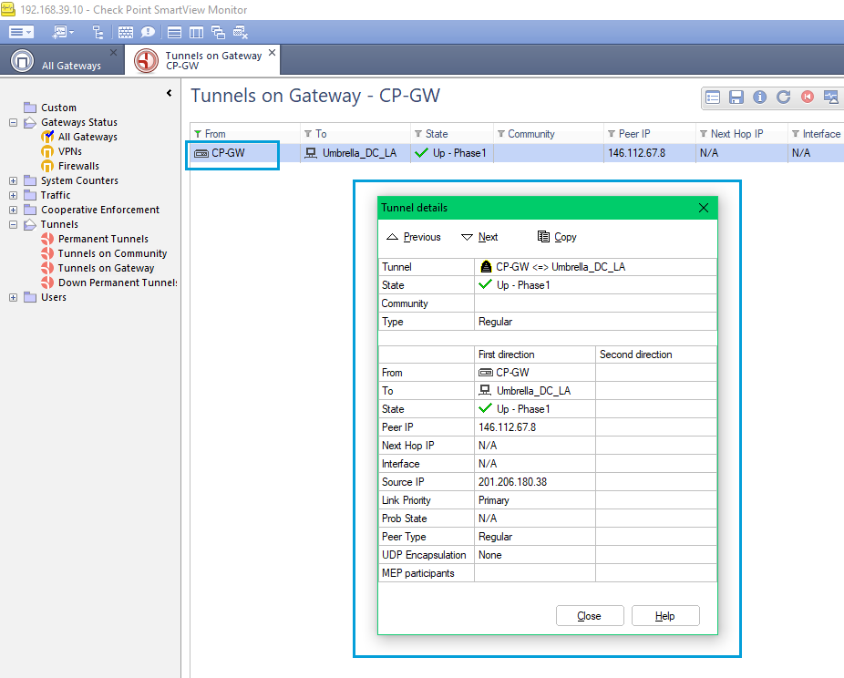
- Double-click the Gateway name and check the Tunnel Status.
Updated almost 2 years ago